EasyManuals Logo

Allen-Bradley 1746-NT8 User Manual

Allen-Bradley 1746-NT8
110 pages
To Next Page IconTo Next Page
To Previous Page IconTo Previous Page
Page #25 background imageLoading...
Page #25 background image
Publication 1746-UM022B-EN-P - January 2005
Installing And Wiring Your Module 2-7
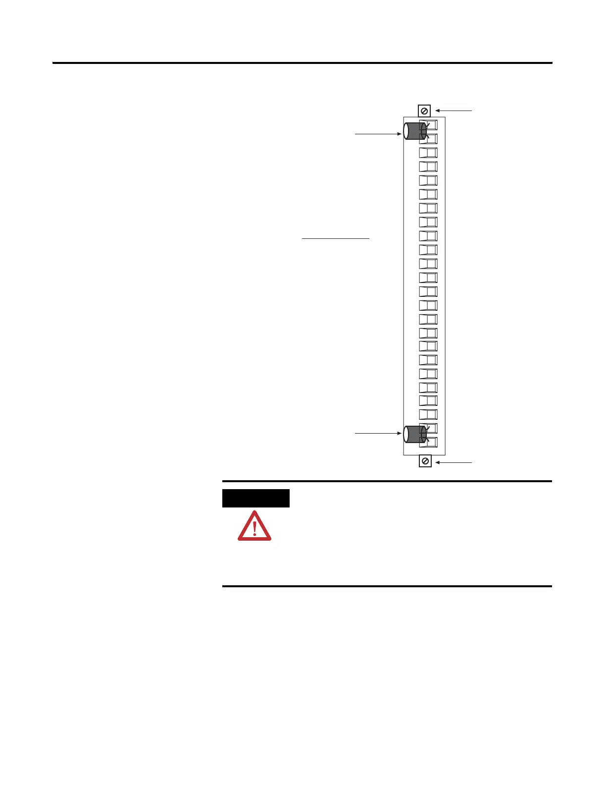
Terminal block diagram with CJC sensors
ATTENTION
Possible Equipment Operation
Before wiring your module, always disconnect
power from the SLC 500 system and from any other
source to the module.
Failure to observe this precaution can cause
unintended equipment operation and damage.
Recommended Torque:
wiring screws: 0.25 Nm (2.2 in-lb)
release screws: 0.25 Nm (2.2 in-lb)
Terminal Block
Release Screws
CJC Sensors
CJC Sensors
Terminal Block
Release Screws

Table of Contents

Questions and Answers:

Question and Answer IconNeed help?

Do you have a question about the Allen-Bradley 1746-NT8 and is the answer not in the manual?

Allen-Bradley 1746-NT8 Specifications

General IconGeneral
BrandAllen-Bradley
Model1746-NT8
CategoryI/O Systems
LanguageEnglish

Related product manuals