Publication 1747-UM006B-EN-P - June 2003
8-14 Application Examples
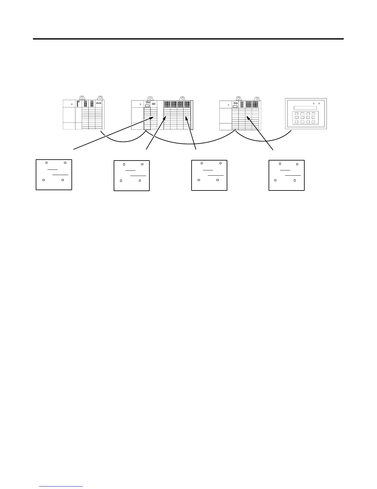
Shown below are examples of how the labels are filled out.
The meter is connected to output 1. The switch is connected to input 17. Bulb 2 is connected to output 12. Bulb 1 is connected to output 4.
The 0–7 and 8–15 boxes are
checked because the module
requires more than one byte of
image.
The SN Slot is 3 because that is the
slot the scanner occupies in the
local SLC chassis.
The SN Words are 14, 15 because
they are the SN image words
assigned to the NIO41. These values
are determined by converting the
module’s logical rack and logical
group numbers (logical rack 1, G6,
G7) to the corresponding SN words.
The 0–7 and 8–15 boxes are
checked because the module
requires more than one byte of
image. Bits 16 to 31 must be
converted to bits 0 to 15 in the SN
image, and the next word (word 17)
used for the I/O reference.
(1)
The SN Slot is 3 because that is the
slot the scanner occupies in the
local SLC chassis.
The SN Words are 16, 17 because
they are the SN image words
assigned to the IV32. These values
are determined by converting the
module’s logical rack and logical
group numbers (logical rack 2, GO,
G1) to the corresponding SN words.
The 0–7 and 8–15 boxes are
checked because the module
requires more than one byte of
image.
The SN Slot is 3 because that is the
slot the scanner occupies in the
local SLC chassis.
The SN Word is 19 because sit is
the SN image word assigned to the
OA16. The value is determined by
converting the module’s logical rack
and logical group numbers (logical
rack 2, G3) to the corresponding SN
word.
The 8–15 box is checked because
the module requires the most
significant byte of image. Bits 0 to 7
must be converted to bits 8 to 15 in
the SN image.
(2)
The SN Slot is 3 because that is the
slot the scanner occupies in the
local SLC chassis.
The SN Word is 0 because it is the
SN image word assigned to the
IO12. These values are determined
by converting the module’s logical
rack and logical group numbers
(logical rack 0, G0) to the
corresponding SN word.
(1) Input bits 16 to 31 must be converted to 0 to 15 by subtracting 16. Therefore, Input Bit 17 is converted to 1.
(2) Input and Output bits 0 to 7 must be converted to 8 to 15 by adding 8. Therefore, Input bit 4 is converted to 12.
012 3
01 234 56
012 3
SLC 5/02
1746-OW8
1746-IA8
1747-SN
ASB 1
1746-NIO4I
1746-IV32
1746-OV32
1746-OB16
1746-OA16
ASB 2
1746-OA8
1746-IO12
1746-IA16
EMPTY
RediPANEL
BT Discrete
0 – 7 8 – 15
SN Slot
SN Word(s)
3
14, 15
Remote SLC System
TM
✓
✓
✓
0 – 7 8 – 15
SN Slot
SN Word(s)
3
16, 17
Remote SLC System
BT Discrete
✓
✓
✓
TM
0 – 7 8 – 15
SN Slot
SN Word(s)
3
19
Remote SLC System
BT Discrete
✓
✓
✓
TM
0 – 7 8 – 15
SN Slot
SN Word(s)
3
0
Remote SLC System
BT Discrete
✓
✓
TM
Artisan Technology Group - Quality Instrumentation ... Guaranteed | (888) 88-SOURCE | www.artisantg.com

 Loading...


