Publication 1747-UM006B-EN-P - June 2003
Configuration 4-9
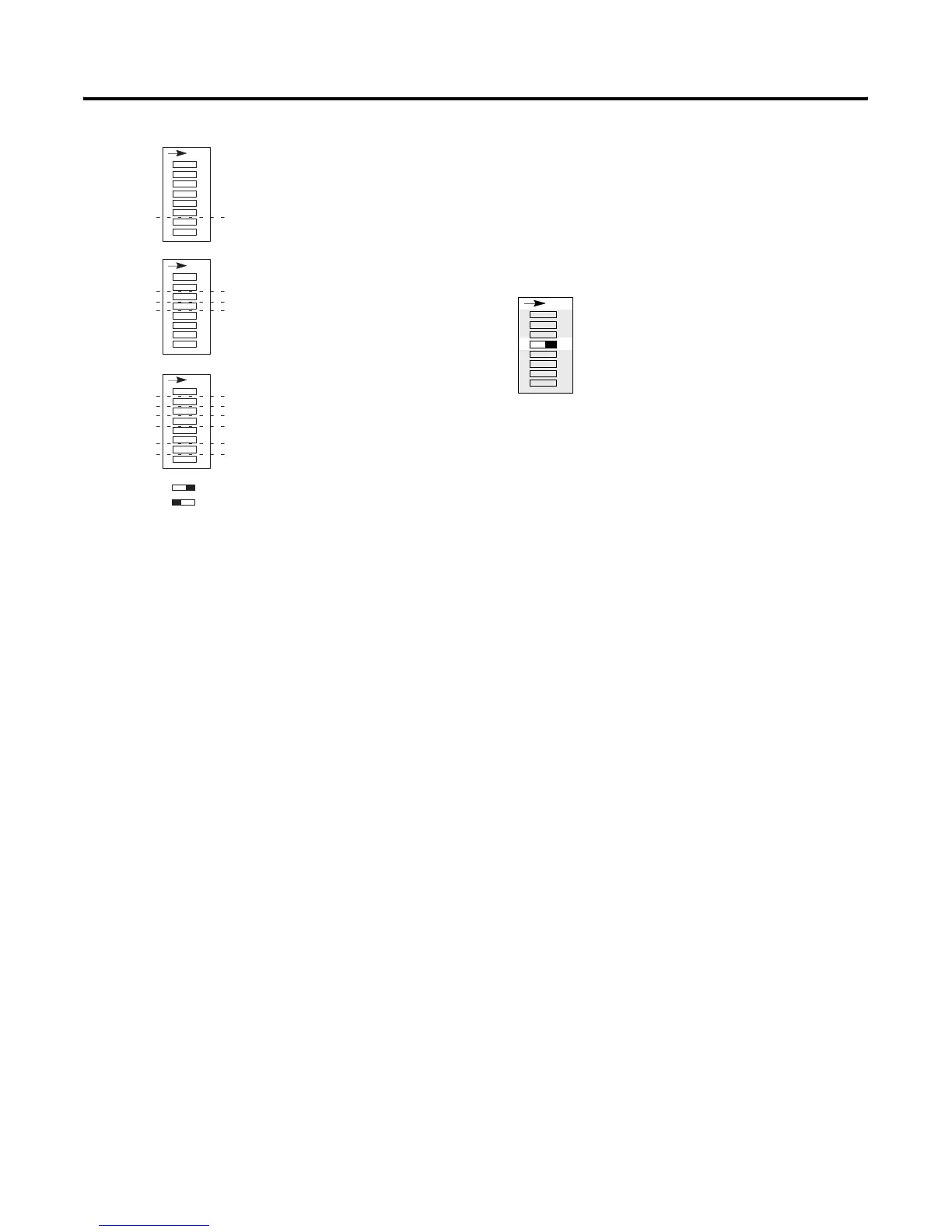
Reserved (SW2-4)
SW2 switch 4 must remain in the ON position.
Reserved DIP Switch Setting
ASB Module Image Size (SW2-5, 6, 7, 8)
SW2 switches 5 through 8 determine the size of the 1747-ASB
module's image that is reserved in the scanner.
You must also make sure you do not exceed the maximum logical
rack number, described on page 4-11.
Image size selection examples are found on page 4-12.
Examples of odd size chassis/images are provided, starting on page
4-13.
41 2345678
SW1 SW2 SW3
1 23 5678 1 2345678
O
N
O
N
O
N
Specialty I/O Mode
I/O Module Keying
Addressing Mode
Last Chassis/PLC-3 Backup
Link Response
Processor Restart Lockout
Hold Last State
Baud Rate
Primary/Complementary Chassis
ASB Module Image Size
Logical Group Number
Logical Rack Number
ON
OFF
Reserved
SW2
Reserved
41 23 5678
O
N
Artisan Technology Group - Quality Instrumentation ... Guaranteed | (888) 88-SOURCE | www.artisantg.com

 Loading...


