Publication 1747-UM006B-EN-P - June 2003
Configuration 4-19
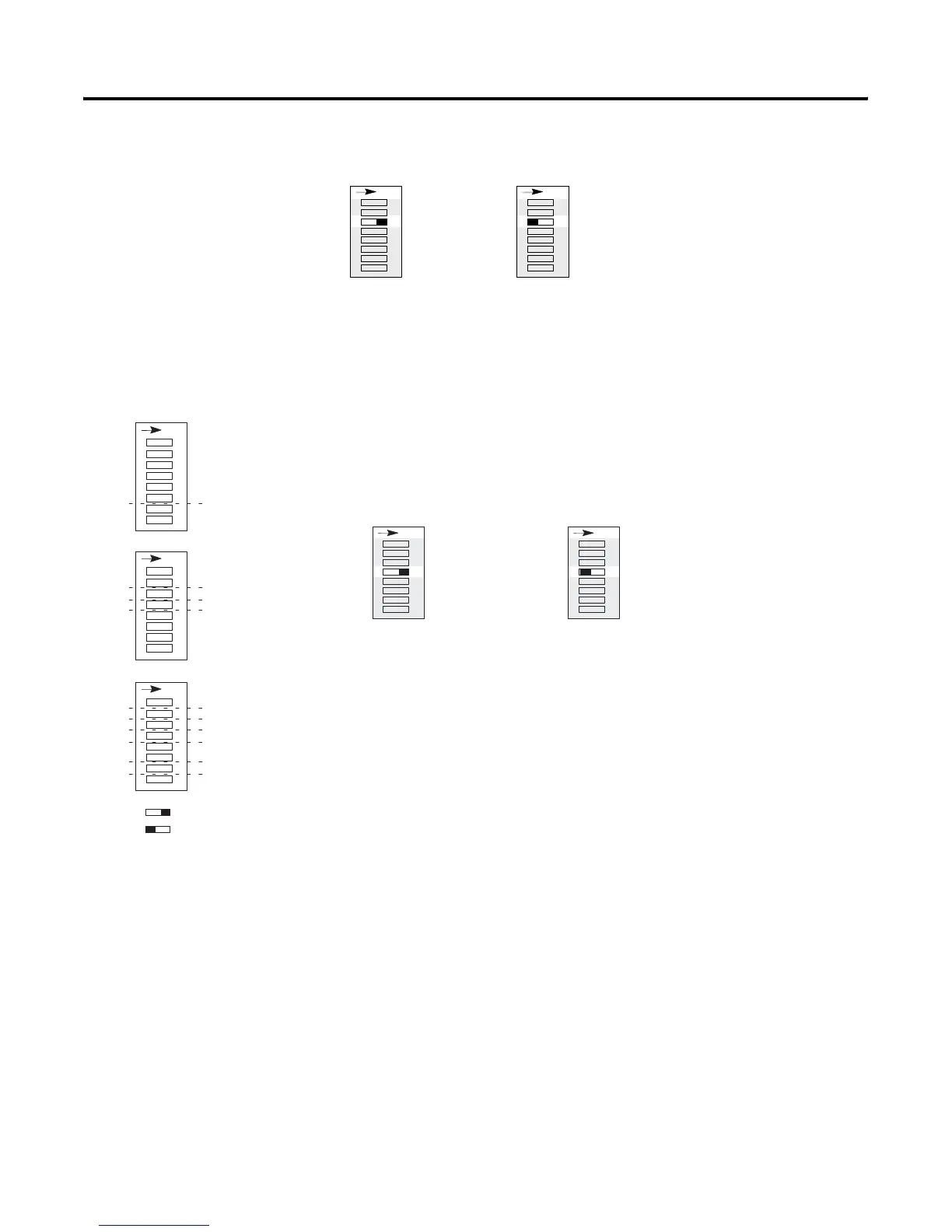
Link Response Time DIP Switch Setting
The 1747-ASB module is shipped from the factory with the default
position ON (restricted).
Last Chassis
SW3 switch 4 is used for last chassis selection when the 1747-ASB
module is connected to a PLC-2, PLC-5, or SLC scanner (Catalog
Number 1747-SN)..
The 1747-ASB module is shipped from the factory with the default
position ON (not last chassis).
A 1747-ASB module should be configured as the last chassis when:
• Its image crosses logical rack boundaries and no other adapter
uses a higher group number within its last logical rack.
• It uses a portion of a logical rack and no other adapter uses a
higher group number within that logical rack.
SW3
Restricted
41 23 5678
O
N
SW3
Unrestricted
41 23 5678
O
N
SW1 SW2 SW3
1 2 3 4 5 6 7 8
O
N
Specialty I/O Mode
I/O Module Keying
Addressing Mode
Last Chassis/PLC-3 Backup
Link Response
Processor Restart Lockout
Hold Last State
Baud Rate
Primary/Complementary Chassi
ASB Module Image Size
Logical Group Number
Logical Rack Number
ON
OFF
Reserved
1 2 3 4 5 6 7 8
O
N
1 2 3 4 5 6 7 8
O
N
SW3
Not Last Chassis
41 23 5678
O
N
SW3
Last Chassis
41 23 5678
O
N
Artisan Technology Group - Quality Instrumentation ... Guaranteed | (888) 88-SOURCE | www.artisantg.com

 Loading...


