Publication 1747-UM006B-EN-P - June 2003
4-20 Configuration
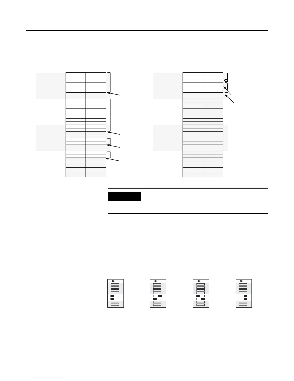
The following examples illustrate last chassis conditions.
Addressing Mode (SW3-5,6)
SW3 switches 5 and 6 determine the addressing mode of 2-slot, 1-slot,
or 1/2-slot.
Addressing Mode DIP Switch Settings
The 1747-ASB module is shipped from the factory with the default
position selected for 1-slot addressing.
1747-ASB Module 2
Scanner Image
1747-ASB Module 1
1747-ASB Module 2
1747-ASB Module 3
1747-ASB Module 4
Last Chassis
Group 2
Group 3
Group 0
Group 1
Group 6
Group 4
Group 5
Group 7
Logical
Rack 1
Group 7
Group 5
Group 6
Group 3
Group 4
Group 1
Group 2
Group 0
Logical
Rack 0
Logical
Rack 2
Group 2
Group 3
Group 0
Group 1
Group 6
Group 4
Group 5
Group 7
Group 7
Group 5
Group 6
Group 3
Group 4
Group 1
Group 2
Group 0
Logical
Rack 3
Scanner Image
Last Chassis
1747-ASB Module 1
Last Chassis
Last Chassis
Not Last Chassis
Not Last Chassis
Group 2
Group 3
Group 0
Group 1
Group 6
Group 4
Group 5
Group 7
Logical
Rack 1
Group 7
Group 5
Group 6
Group 3
Group 4
Group 1
Group 2
Group 0
Logical
Rack 0
Logical
Rack 2
Group 2
Group 3
Group 0
Group 1
Group 6
Group 4
Group 5
Group 7
Group 7
Group 5
Group 6
Group 3
Group 4
Group 1
Group 2
Group 0
Logical
Rack 3
Bit Number (Decimal)
07815
Bit Number (Octal)
0717 10
Bit Number (Decimal)
07815
Bit Number (Octal)
0717 10
1747-ASB Module 3
Not Last Chassis
IMPORTANT
When using complementary I/O, do not configure a
primary chassis as the last chassis, otherwise a
1747-ASB module error occurs.
SW3
1/2-slot
41 23 5678
O
N
SW3
Invalid
41 23 5678
O
N
SW3
1-slot
41 23 5678
O
N
SW3
2-slot
41 23 5678
O
N
Artisan Technology Group - Quality Instrumentation ... Guaranteed | (888) 88-SOURCE | www.artisantg.com

 Loading...


