1 Publication 1747-UM006B-EN-P - June 2003
Chapter
4
Configuration
This chapter presents the configuration options made through the
various DIP switch settings.
DIP Switch Information
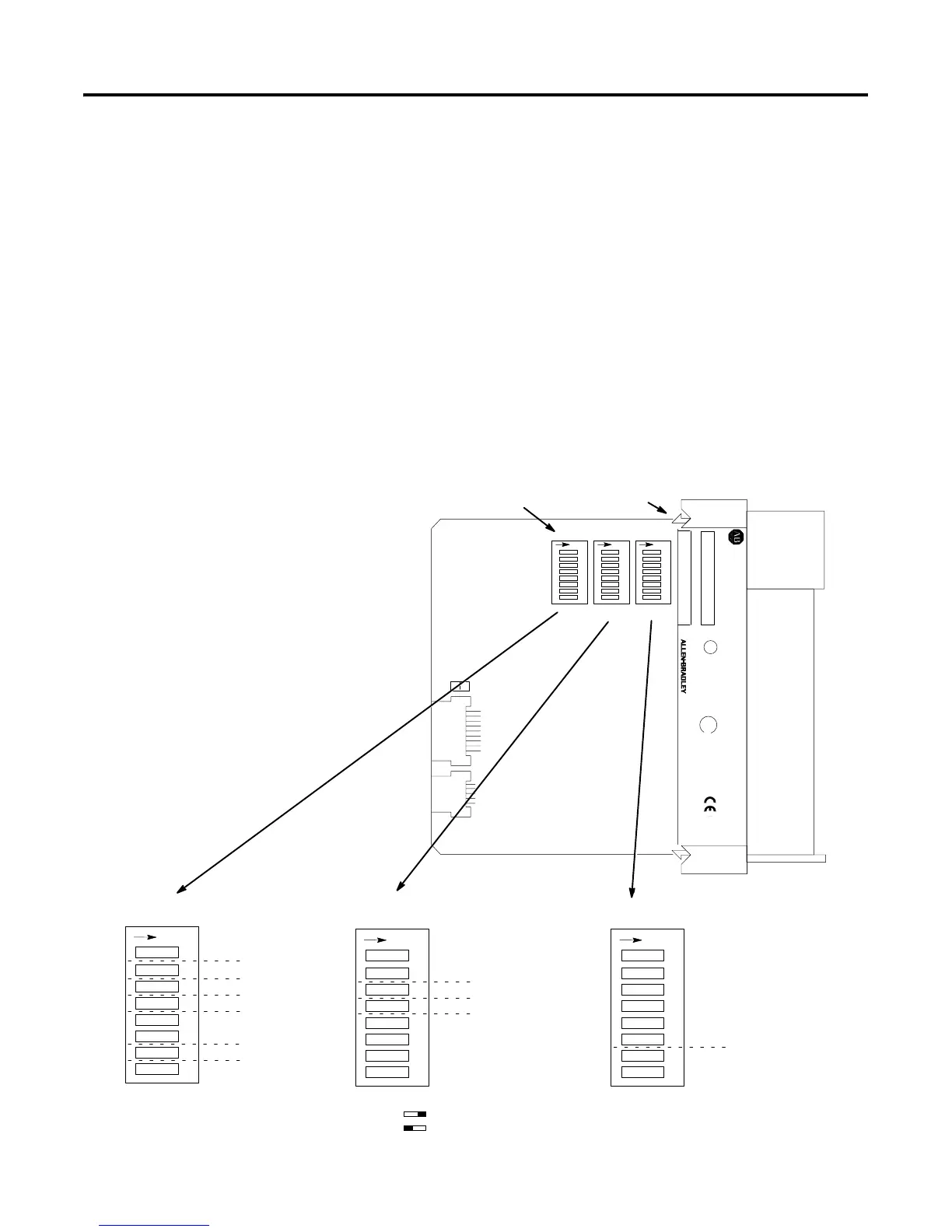
The 1747-ASB module parameters are configured by three DIP
switches, shown below. To assist you in the configuration of multiple
1747-ASB modules, a configuration worksheet is provided in
Appendix C.
1
O
N
2456783
SW1
SW2
SW3
Logical Rack Number Bit 5 (MSB)
Logical Rack Number Bit 4
Logical Rack Number Bit 3
Logical Rack Number Bit 2
Logical Rack Number Bit 1
Logical Rack Number Bit 0 (LSB)
Logical Group Number Bit 1 (MSB)
Logical Group Number Bit 0 (LSB)
1
O
N
2456783
Baud Rate Bit 1 (MSB)
Baud Rate Bit 0 (LSB)
Primary/Complementary SLC Chassis
Reserved
ASB Module Image Size Bit 3 (MSB)
ASB Module Image Size Bit 2
ASB Module Image Size Bit 1
ASB Module Image Size Bit 0 (LSB)
1
O
N
2456783
Hold Last State
Processor Restart Lockout
Link Response
Last Chassis/PLC-3 Backup
Addressing Mode Bit 1 (MSB)
Addressing Mode Bit 0 (LSB)
Specialty I/O Mode
I/O Module Keying
SLC 500
CAT SER
SERIAL NO. FRN
U
L
SA
DIP Switches
1 2345678
SW1
O
N
1 2345678
SW2
O
N
1 2345678
SW3
O
N
IMPORTANT:
INSTALL IN SLOT ZERO OF MODULAR CHASSIS ONLY
REMOTE I/O ADAPTER MODULE
FAC 1M MADE IN USA
CURRENT REQUIREMENT: 375mA
LISTED IND. CONT. EQ.
FOR HAZ. LOC. A196
CLASS 1, GROUPS A, B, C AND D, DIV. 2
OPERATING
TEMPERATURE
CODE T3C
ON
OFF
Self-Locking Tab
Artisan Technology Group - Quality Instrumentation ... Guaranteed | (888) 88-SOURCE | www.artisantg.com

 Loading...


