Publication 1747-UM006B-EN-P - June 2003
3-4 Addressing
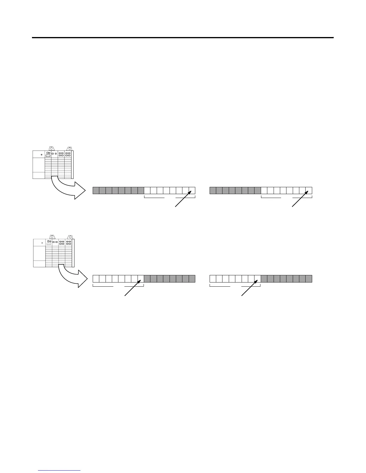
2-Slot Addressing
When the 1747-ASB module is configured for 2-slot addressing, the
processor addresses two chassis slots as one logical group. Each slot,
beginning with slot 1, is sequentially assigned one byte (8 bits) of the
1747-ASB module's input and output image. Each terminal on a
discrete I/O module installed in a slot is assigned a bit within the byte,
beginning with the least significant bit. 2-slot addressing is designed
to accommodate I/O modules whose image size is one byte or less.
Slot 1
Slot 1 is assigned to the low byte of the first logical
group of the 1747-ASB module ’s image, beginning
with bit 0 (the LSB).
Slot 1
151413121110987 654 3210
Slot 2 is assigned to the high byte of the first
logical group of the 1747-ASB module’s
image, beginning with bit 8 decimal, 10 octal.
Slot 2
151413121110987 654 3210
Slot 2
Each terminal is assigned a bit,
beginning with the least significant bit.
Each terminal is assigned a bit,
beginning with the least significant bit.
group 0
group 0
Slot 1
15141312111098765 432 10
Slot 2
15141312111098765 432 10
Each terminal is assigned a bit,
beginning with the least significant bit.
group 0
group 0
Each terminal is assigned a bit,
beginning with the least significant bit.
Decimal
Octal
Decimal
Octal
70
70
70
70
10
10
10
10
17
17
17
17
Input Image
Input Image
Output Image
Output Image
Decimal
Octal
Decimal
Octal
Artisan Technology Group - Quality Instrumentation ... Guaranteed | (888) 88-SOURCE | www.artisantg.com

 Loading...


