Publication 1747-UM006B-EN-P - June 2003
6-8 Start-Up and Operation
2. Apply power to all chassis.
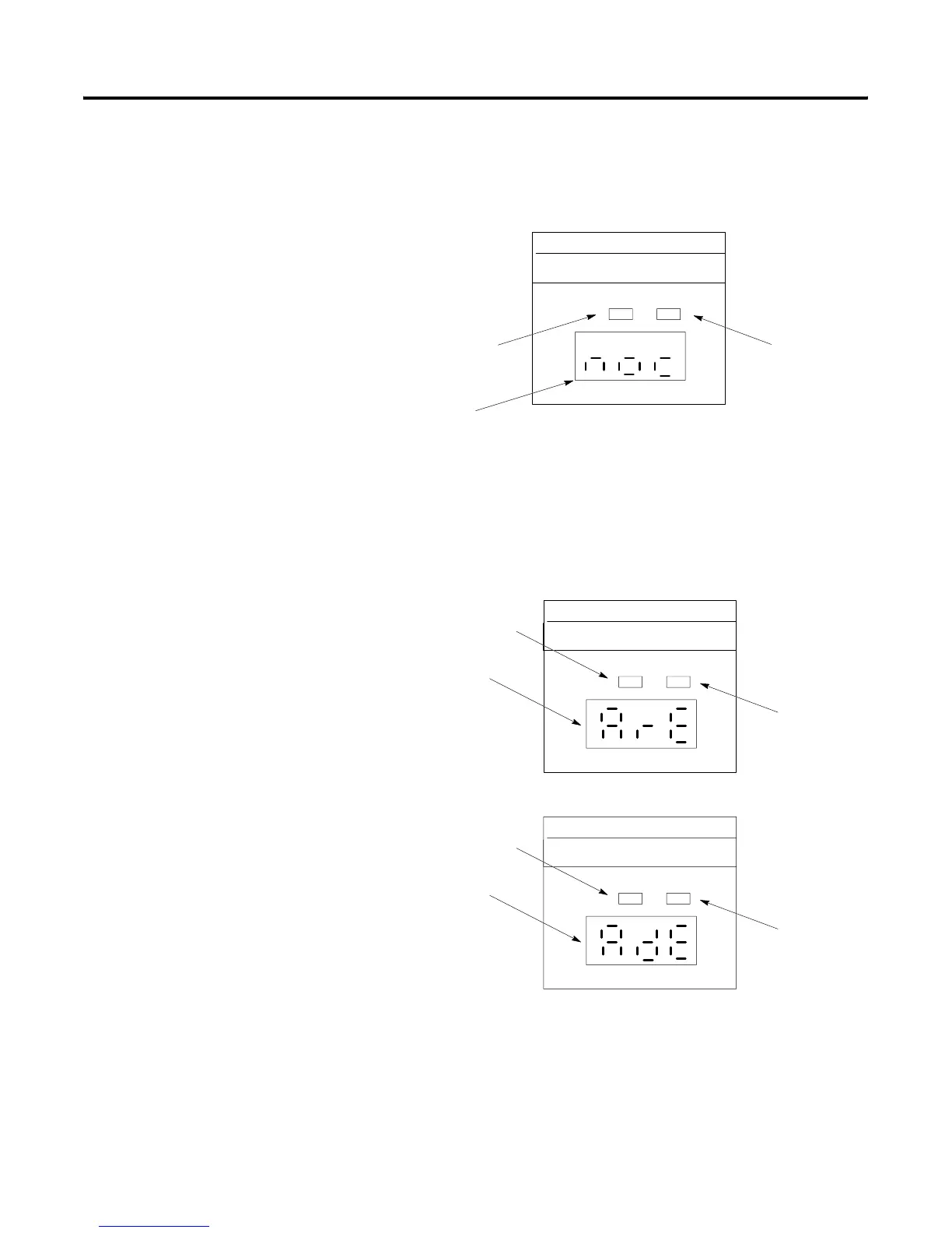
3. After completing power up diagnostics, the 1747-ASB module
display appears as shown below:
4. Configure the PLC or SLC processor so that the scanner will
communicate on the RIO link with the 1747-ASB module. Place
the processor in the test mode. The 1747-ASB module display
appears as shown below:
ADAPTER
COMM FAULT
STATUS
Red Fault LED is off.
Status display indicates no RIO
communications condition.
Green COMM LED is off.
Status display indicates no RIO
communications condition.
ADAPTER
COMM FAULT
STATUS
ADAPTER
COMM FAULT
STATUS
Red Fault LED is off.
Green COMM LED is off.
Status display indicates
a reset, adapter reset
condition.
Red Fault LED is off.
Green COMM LED is off.
Status display indicates
reset, adapter decide
ondition.
Artisan Technology Group - Quality Instrumentation ... Guaranteed | (888) 88-SOURCE | www.artisantg.com

 Loading...


