Rockwell Automation Publication 1769-UM021G-EN-P - October 2015 149
Use I/O Modules with CompactLogix 5370 L1 Controllers Chapter 7
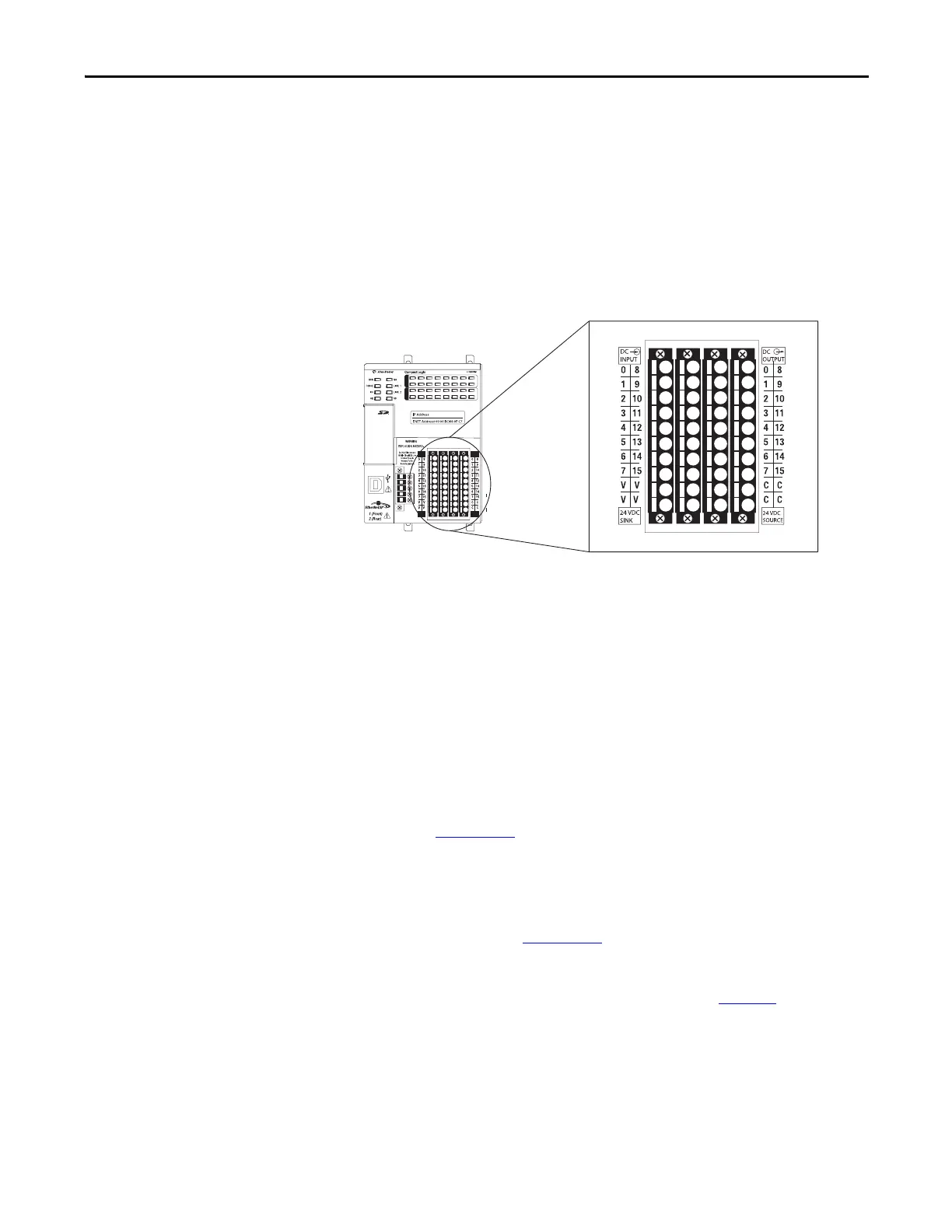
Embedded I/O Modules
CompactLogix 5370 L1 controllers provide an embedded power supply and an
embedded I/O module with these points:
• 16 sinking 24V DC digital input points
• 16 sourcing 24V DC digital output points
The following diagram shows the wiring terminals on the embedded
I/O module.
Consider the following when you connect input or output devices to the
embedded I/O modules of your CompactLogix 5370 L1 controller:
• You must connect an external 24V DC power source to the FP+ and FP-
terminals on the removable connector on the controller to power input
and output devices that are connected to the embedded I/O modules on
the controller:
– Series A for L16ER, L18ER, and L18ERM controllers require an extra
external 24V DC power source for the FP+ and FP- terminal
connections. For more information on how to connect an extra external
power source for series A L1 controller to the FP+ and FP- terminals,
see Appendix
C.
– Series B controllers use the external 24V DC power source that is
connected to the VDC+ and VDC- terminals on the controller for the
FP+ and FP- terminal connections. Series B controllers can also use an
extra external 24V DC power source for the FP+ and FP- terminal
connections. See Appendix
C for more information on how to connect
the extra external power source to the FP+ and FP- terminals. For more
information on how to connect the external power source to the FP+
and FP- terminals on the series B controller, see page 146
.
 Loading...