94 Rockwell Automation Publication 2080-UM004C-EN-E - March 2015
Appendix B Quickstart
Setup and Wiring
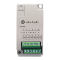
1. Insert the high speed counter plug-in module into the designated slot in
your Micro800 controller.
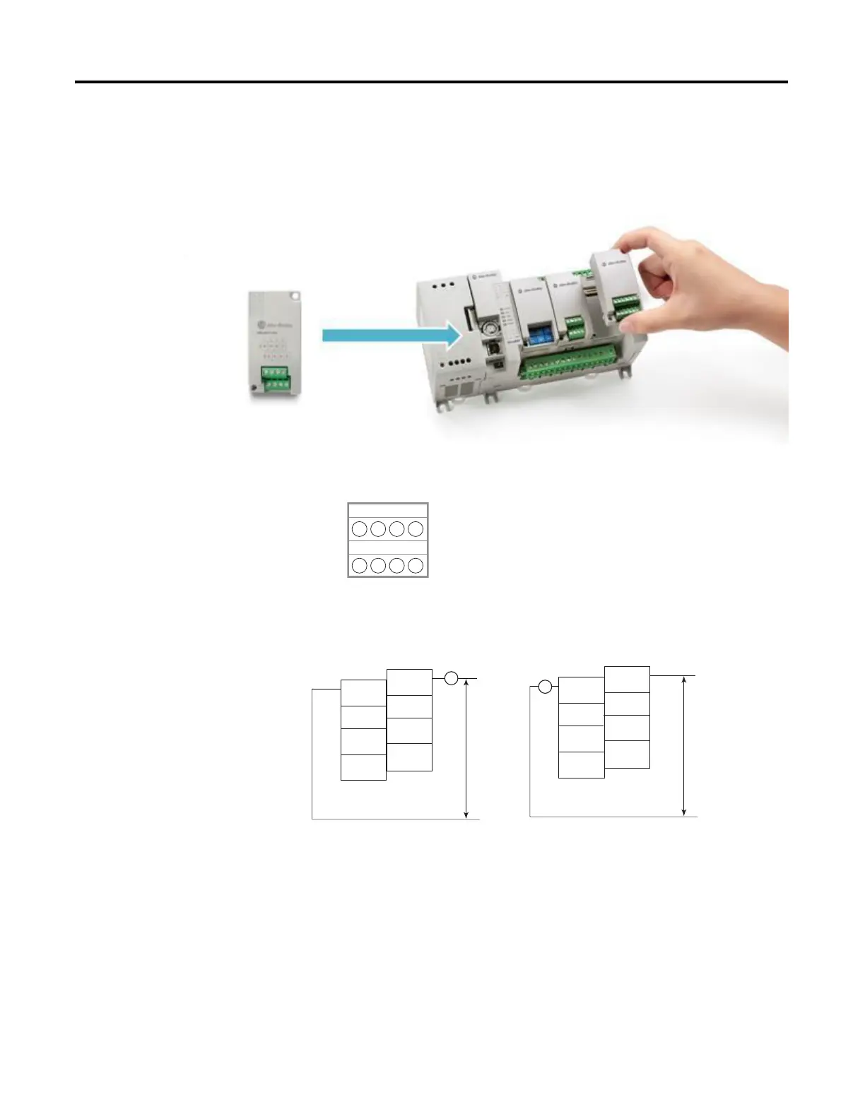
2. Wire your plug-in to your controller as shown in the following diagram.
1 2 3 4
1 2 3 4
Back
Front
(View into terminal block)
Pin A1 0- Pin B1 0+
Pin A2 A- Pin B2 A+
Pin A3 B- Pin B3 B+
Pin A4 Z- Pin B4 Z+
B
A
0-
A-
B-
Z-
A+
B+
Z+
0+
DC(+)
DC(-)
CR
CR
0-
A-
B-
Z-
A+
B+
Z+
0+
DC(+)
DC(-)
Sinking Output Wiring
Sourcing Output Wiring
NOTE: Output functionality is
not currently supported and is
dependent on availability of
UDFB support.
 Loading...