Rockwell Automation Publication 2100-IN012G-EN-P - August 2016 117
Bulletin 140G Unit Assembly Instructions Appendix A
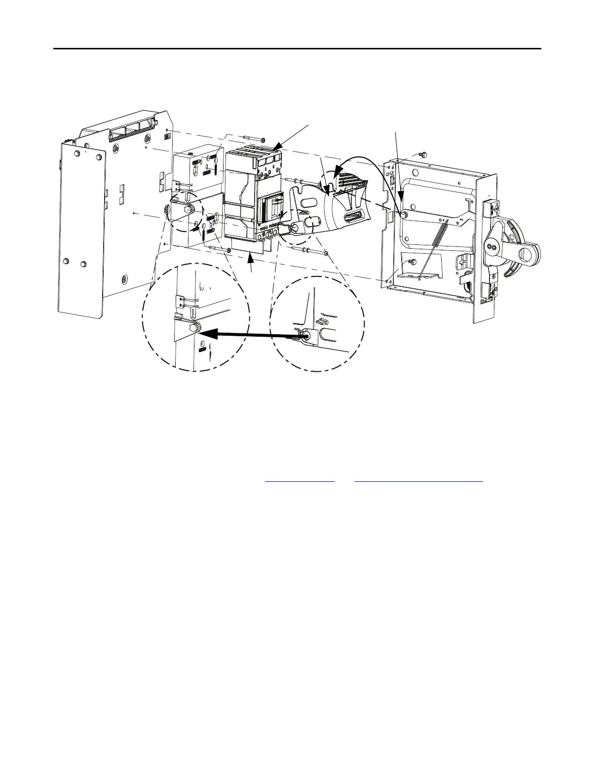
10. Move the circuit breaker/bale to the ‘OFF’ position.
11. Engage the linkage to the bale.
12. Verify that the circuit breaker operates correctly.
See Verif y Operation
and Adjust Circuit Breaker Position.
13. Snap the auxiliary contacts to the bracket.
14. Attach the line-side wiring and tighten to 53 lb•in (6 N•m) for G and H
frame units; tighten to 71 lb•in (8 N•m) for J Frame units.
15. Add the line terminal cover to the line side (not included in the kit).
16. Insert the terminal cover screw (not provided with the kit), and tighten
to 8 lb•in (0.90 N•m).
17. Attach the load-side wiring and tighten to 53 lb•in (6 N•m) for G and
H frame units; tighten to 71 lb•in(8 N•m) for J frame units.
18. Install the load side phase separators on the load side (not supplied with
the kit).
Verify that the phase separators are pushed down completely so that they
are flush with the cover.
Base
Circuit Breaker
Bale
Linkage
Click
Line Terminal Cover
Phase
Separators
TIP If wired accessories are included in the circuit breaker, route accessory wires
under the circuit breaker in the ‘trough’ in the base.
Verify that all accessory wires exit on the left side of the assembly, above the
bale connection point. Use wire ties to avoid tangled wires in the unit.

 Loading...


