Rockwell Automation Publication 1756-RM012B-EN-P - April 2018 23
Chapter 3
Safety I/O for the GuardLogix Control System
Before you operate a GuardLogix safety system with Safety I/O devices, you
must first read, understand, and follow all safety information in the product
documentation for those products.
Safety I/O devices can be connected to safety input and output devices, like
sensors and actuators. The GuardLogix controller monitors and controls the
devices. For safety data, I/O communication is performed through safety
connections by using the CIP Safety protocol; safety logic is processed in the
GuardLogix controller.
Typical Safety Functions of
Safety I/O Devices
The following is treated as the safe state by Safety I/O devices:
•Safety outputs: OFF
• Safety input data to controller: OFF
Use Safety I/O devices for applications that are in the safe state when the safety
output turns OFF.
Diagnostics
Safety I/O devices perform self-diagnostics when the power is turned ON and
periodically during operation. If a diagnostic failure is detected, safety input
data (to the controller) and local safety outputs are set to their safe state (OFF).
Topic Page
Typical Safety Functions of Safety I/O Devices 23
Reaction Time 24
Safety Considerations for Safety I/O Devices 25
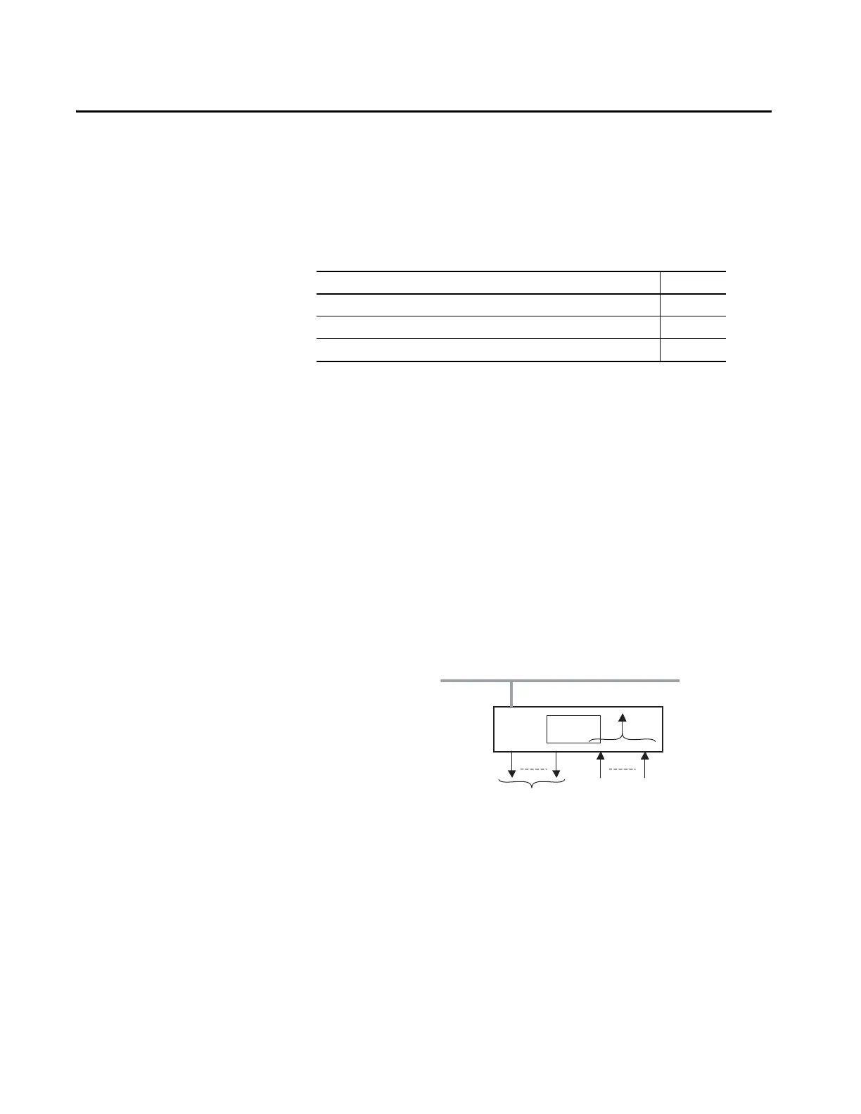
Safety Network
Safety Status
Safety Output, OFF
Safety
Input
Data
 Loading...