82 Rockwell Automation Publication 1756-RM012B-EN-P - April 2018
Appendix C Reaction Times
The Logix system reaction time for any simple input to logic to output chain
consists of these five components:
1. Safety input device reaction time (plus input delay time, if applicable)
2. Safety Input Connection Reaction Time Limit
(Read from the Module Properties dialog box in the Studio 5000 Logix
Designer application, this value is a multiple of the safety input device
connection RPI.)
3. Controller reaction time (see Safety Task Reaction Time on page 13
)
4. Safety Output Connection Reaction Time Limit
(Read from the Module Properties dialog box in the Studio 5000 Logix
Designer application, this value is a multiple of the safety task period.)
5. Safety output device reaction time
Logic Chain Using Produced/Consumed Safety Tags
This section describes the Logix system reaction time for any input to
controller A logic to controller B logic to output chain.
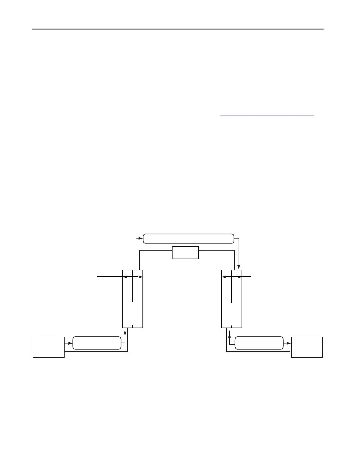
Figure 26 - Logix System Reaction Time for Input to Controller A Logic to Controller B Logic to
Output Chain
The Logix system reaction time for any input to controller A logic to
controller B logic to output chain consists of these seven components:
1. Safety input device reaction time (plus input delay time, if applicable)
2. Safety Input Connection Reaction Time Limit
3. Safety Task Period plus Safety Task Watchdog time for Controller A
1. Safety Input
Device Delay
7. Safety Output
Device Delay
2. Safety Input Connection
Reaction Time Limit
6. Safety Output Connection
Reaction Time Limit
Safety Network
4. P/C Safety Connection Reaction Time Limit
Ethernet
Network
Ethernet
Switch
Ethernet
Network
Safety Network
GuardLogix
Controller A
GuardLogix
Controller B
3. Safety Task Period +
Safety Task Watchdog
5. Safety Task Period +
Safety Task Watchdog
 Loading...