Rockwell Automation Publication 1756-RM012B-EN-P - April 2018 81
Reaction Times Appendix C
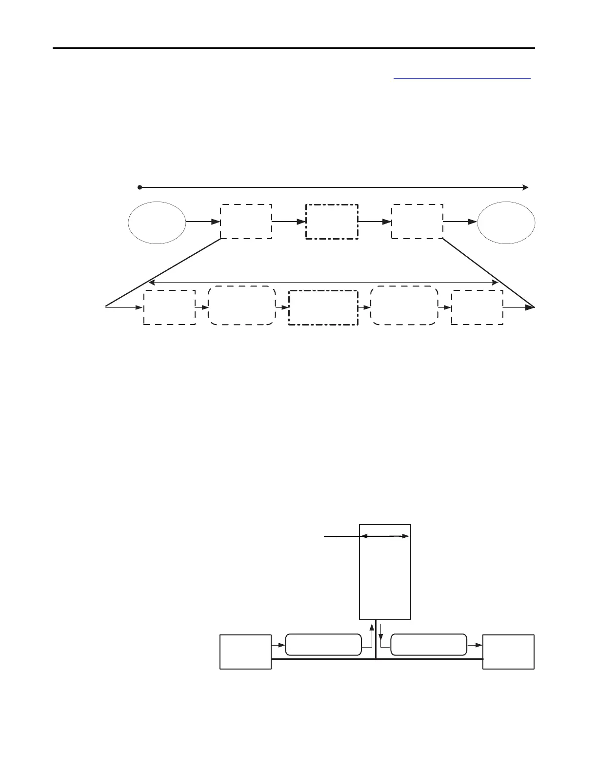
System Reaction Time
To determine the system reaction time (see System Reaction Time on page 13
for details) of any control chain, you must add up the reaction times of all of
components of the safety chain.
System Reaction Time = Sensor Reaction Time + Logix System
Reaction Time + Actuator Reaction Time
Figure 24 - System Reaction Time
Logix System Reaction Time
The following sections provide information on how to calculate the Logix
system reaction time for a simple input-logic-output chain and for a more
complex application by using produced/consumed safety tags in the logic
chain.
Simple Input-logic-output Chain
This section describes the Logix system reaction time for any simple input to
logic to output chain.
Figure 25 - Logix System Worst-case Reaction Time for Simple Input to Logic to Output
System Reaction Time
Sensor Reaction
Time
Input Reaction
Time
Safety Task
Reaction Time
Output Reaction
Time
Actuator
Reaction Time
Logix System Reaction Time
Input Device
Delay
Input Connection
Reaction Time Limit
Controller
Reaction
Time
Output Connection
Reaction Time Limit
Output Device
Delay
1. Safety Input
Device Delay
5. Safety Output
Device Delay
2. Safety Input Connection
Reaction Time Limit
4. Safety Output Connection
Reaction Time Limit
Safety Network
*A communication module is
required for DeviceNet.
GuardLogix Controller*
3. Controller
Reaction Time
 Loading...