28 Rockwell Automation Publication DNET-IN001B-EN-P - January 2012
Chapter 2 Install a 1769 DeviceNet Communication Module
System Assembly
The module can be attached to an adjacent controller, power supply, or I/O
module.
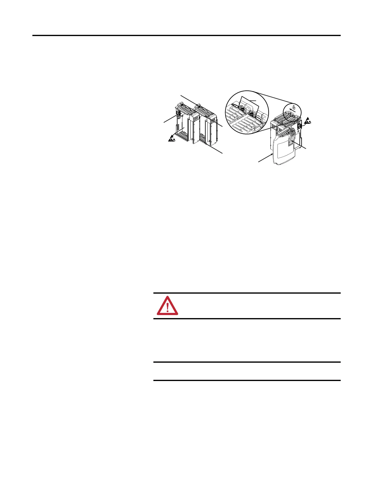
Follow these steps to assemble the Compact I/O system.
1. Disconnect power.
2. Check that the bus lever of the module (A) is in the unlocked (fully right)
position.
3. Use the upper and lower tongue-and-groove slots (B) to secure the
modules together.
4. Move the module back along the tongue-and-groove slots until the bus
connectors (C) line up with each other.
5. Use your fingers or a small screwdriver to push the bus lever back slightly to
clear the positioning tab (D).
6. Move the module’s bus lever fully to the left (E) until it clicks.
Be sure it is locked firmly in place.
7. Attach an end cap terminator (F) to the last module in the system by using
the tongue-and-groove slots as before.
8. Lock the end cap bus terminator (G).
ATTENTION: When attaching I/O modules, it is very important
that the bus connectors are securely locked together to make a
proper electrical connection.
A 1769-ECR or 1769-ECL right or left end cap must be used to
terminate the end of the serial communication bus.

 Loading...


