16 Rockwell Automation Publication 2071-IN001F-EN-P - February 2017
Kinetix 3 Component Servo Drives
This installation applies to TL-Series™ (Bulletin TLY) rotary motors, LDC-Series™ and LDL-
Series™ linear motors, and MP-Series™ (Bulletin MPAS), TL-Series (Bulletin TLAR), and
LDAT-Series actuators.
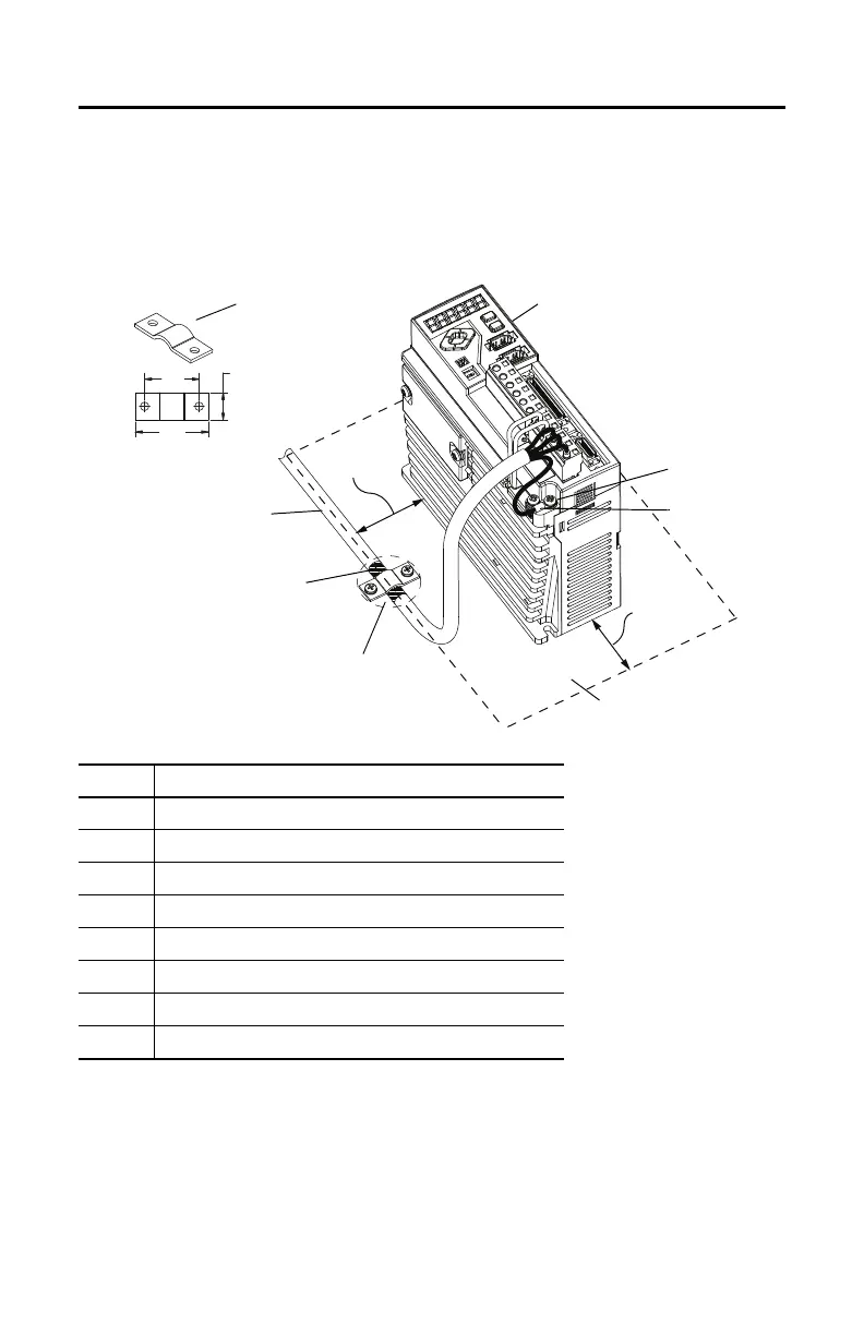
Terminate the input-power ground wire with a ring lug as shown. Attach input power and motor
power grounds to ground screws, and torque to 1.25 N•m (11 lb•in).
Item Description
1 2071-AP4 Kinetix 3 drive shown
2 Motor-power ground clamp
3 Motor power cable
4 Expose 25 mm (1 in.) of cable shield
5 If panel is painted, remove paint to provide metal-to-metal contact
6Sub panel
7Ring lug
8 Ground screw
(1)
(1) 2071-AP0, 2071-AP1, and 2071-AP2 drives have one grounding screw on the heatsink.
2071-AP4, 2071-AP8, 2071-A10, and 2071-A15 drives have two ground screws on the heatsink.
50…75
(2…3)
50…75
(2…3)
34.0
(1.34)
25
(1.0)
12.7
(0.50)
3
6
7
1
4
5
2
8
Dimensions are in mm (in.)
 Loading...


