Rockwell Automation Publication 2071-IN001F-EN-P - February 2017 7
Kinetix 3 Component Servo Drives
Connector Data
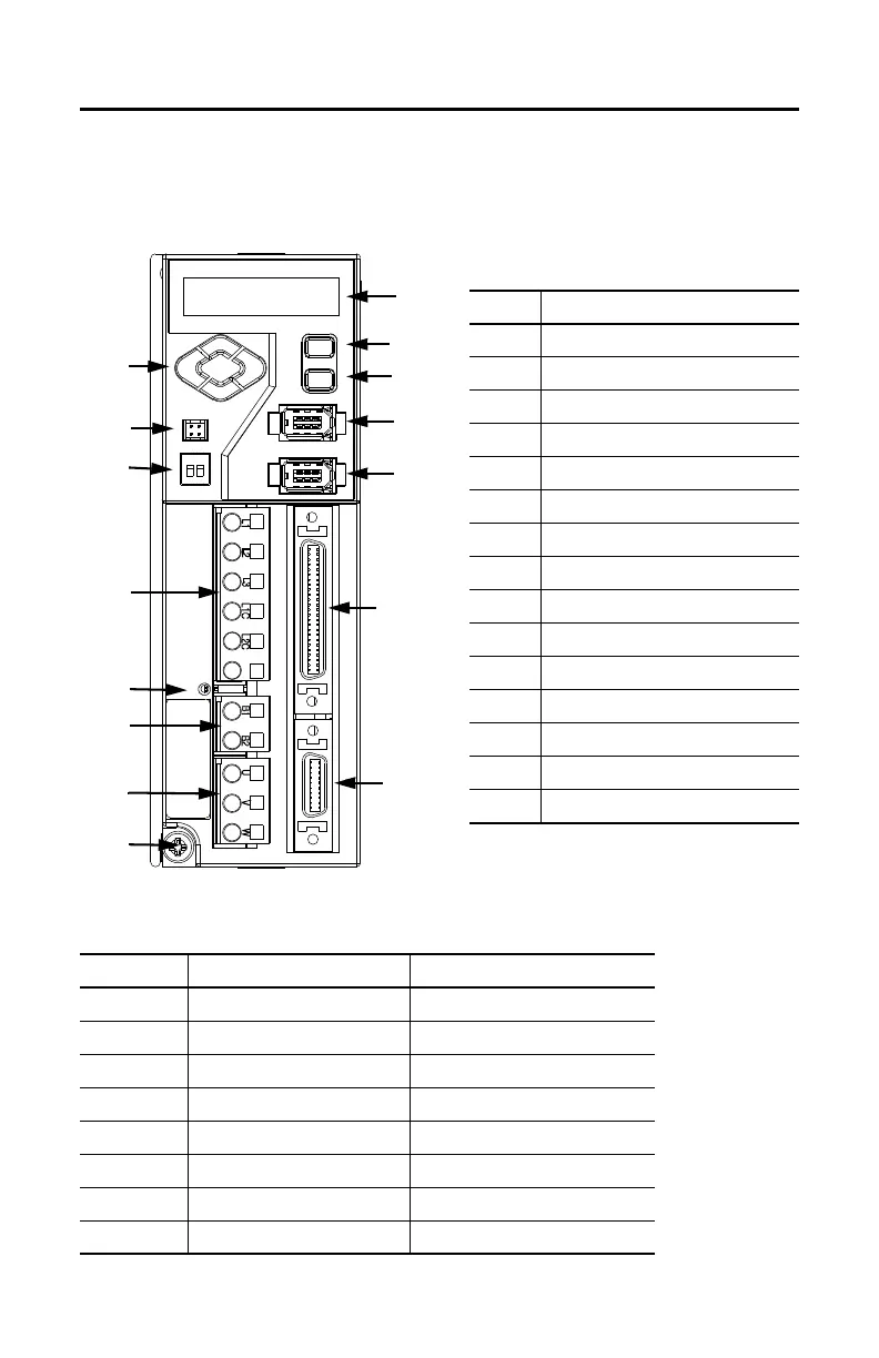
Use this illustration to identify the Kinetix 3 drive features and indicators.
Kinetix 3 Features and Indicators
Kinetix 3 Connectors
Item Description
1 Left/right and up/down keys
2 Analog output (A.out)
3 RS-485 communication termination switch
4 Input power (IPD)
5 Main power indicator
6Shunt power (BC)
7 Motor power (MP)
8 Ground lug
9 Motor feedback (MF)
10 Input/output (I/O)
11 Serial interface (Comm0B) (down)
12 Serial interface (Comm0A) (up)
13 Enter key
14 Mode/set key
15 7-segment status indicator
Designator Description Connector
A.out Analog output 4-pin connector header
IPD AC and control power input 6-pin quick-connect terminal block
BC Shunt power 2-pin quick-connect terminal block
MP Motor power 3-pin quick-connect terminal block
CommOA Serial interface up 6-pin IEEE 1394 connector
CommOB Serial interface down 6-pin IEEE 1394 connector
IOD I/O 50-pin mini-D connector
MF Motor feedback 20-pin mini-D connector
 Loading...


