12 Kinetix 5700 DC-bus Power Supplies
Rockwell Automation Publication 2198-IN009B-EN-P - June 2015
Wiring Requirements
Wire must be copper with 75 C (167 F) minimum rating. Phasing of mains AC power is
arbitrary and earth ground connection is required for safe and proper operation.
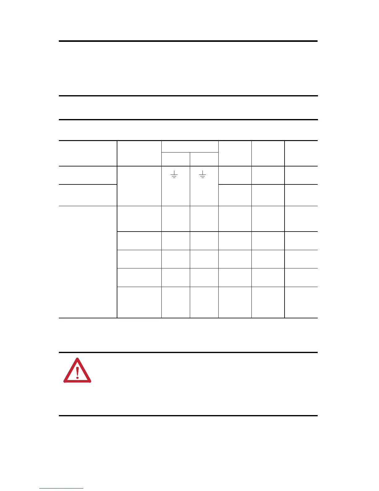
DC-bus Power Supply Wiring Requirements
The National Electrical Code and local electrical codes take precedence over the values and
methods provided.
DC-bus Power Supply
Cat. No.
Description
Connects to Terminals
Wire Size
mm
2
(AWG)
Strip
Length
mm (in.)
Torque
Value
N•m (lb•in)
Pin Signal
2198-P031
2198-P070
Mains input power
6…10
(10…8)
10.0 (0.39)
0.5…0.8
(4.4…7.1)
2198-P141
2198-P208
10…35
(8…2)
20.0 (0.79)
2.5…4.5
(22…40)
2198-Pxxx
PELV/SELV
24V power
(connector plug)
CP-1
CP-2
24V+
24V–
0.5…2.5
(20…14)
7.0 (0.28)
0.22…0.25
(1.9…2.2)
DC Bus power Bus bar
DC–
DC+
N/A
(1)
(1) Shared DC-bus power connections are always made from drive to drive over the bus-bar connection system. These terminals do not receive discrete
wires.
N/A
(1)
N/A
(1)
Contactor enable
EN–
EN+
CONT EN–
CONT EN+
0.14…2.5
(26…12)
7.0 (0.28)
0.4…0.5
(3.5…4.4)
Shunt resistor
RC-1
RC-2
SH
DC+
1.5…6
(16…10)
12.0 (0.47)
0.5…0.6
(4.5…5.3)
Digital inputs
IOD-1
IOD-2
IOD-3
IOD-4
IN1
COM
IN2
COM
0.14…1.5
(26…16)
10.0 (0.39) N/A
(2)
(2) This connector uses spring tension to hold wires in place.
ATTENTION: To avoid personal injury and/or equipment damage, observe the following:
• Make sure that installation complies with specifications regarding wire types, conductor sizes,
branch circuit protection, and disconnect devices. The National Electrical Code (NEC) and local
codes outline provisions for safely installing electrical equipment.
• Use motor power connectors only for connection purposes. Do not use them to turn the unit on
and off.
• Ground shielded power cables to prevent potentially high voltages on the shield.

 Loading...


