6 Kinetix 5700 DC-bus Power Supplies
Rockwell Automation Publication 2198-IN009B-EN-P - June 2015
Minimum Clearance Requirements
The Kinetix 5700 drive system must be spaced by aligning the zero-stack tab and cutout. For
mounting, sizing, and configuring shared-bus configurations, refer to the Kinetix 5700 Servo
Drives User Manual, publication 2198-UM002.
Mount the Kinetix 5700 drive module to the cabinet subpanel with M5 (#10-32) steel bolts
torqued to 4.0 N•m (35.4 lb•in), max.
Drilling Hole Patterns
This section provides hole patterns for Kinetix 5700 drive modules that are mounted in
zero-stack (shared-bus) configurations:
• The DC-bus power supply is always mounted in the far left position.
• Inverter modules with a higher power rating are always mounted to the left of any
inverter module with a lower power rating.
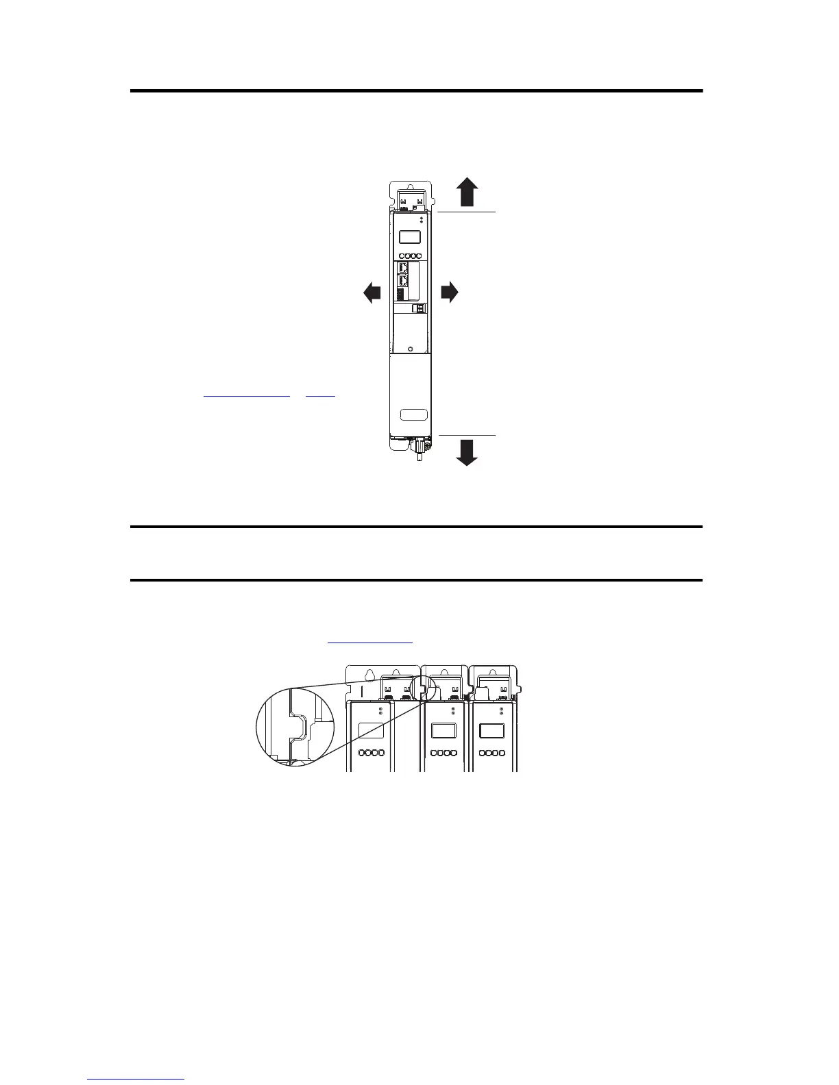
Mount the drive module in an upright position as shown. Do not mount the drive module on
its side.
Clearance right of the
drive is not required.
Clearance left of the
drive is not required.
Kinetix 5700 DC-bus
Power Supply
100 mm (3.94 in.) clearance below
drive for airflow and installation.
40 mm (1.57 in.) clearance above
drive for airflow and installation.
Refer to Product Dimensions
on page 8
for DC-bus power supply dimensions.
Zero-stack Tab and
Cutout Aligned
Shared-bus connection system is
not shown for clarity.
 Loading...


