Kinetix 5700 DC-bus Power Supplies 9
Rockwell Automation Publication 2198-IN009B-EN-P - June 2015
Connector Data
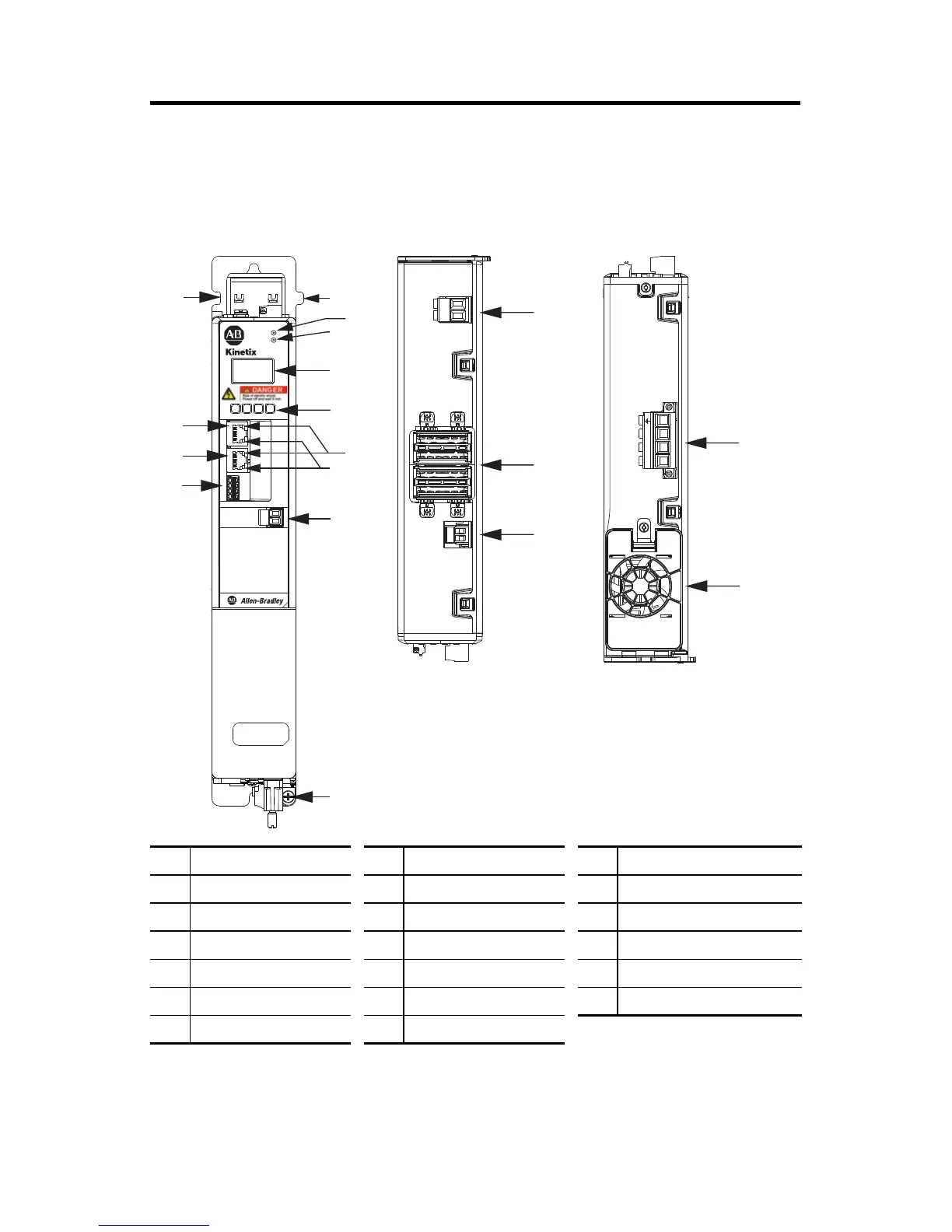
Use this illustration to identify the DC-bus power supply features and indicators.
DC-bus Power Supply Features and Indicators (2198-P031 power supply is shown)
Item Description Item Description Item Description
1 Digital inputs (IOD) connector 7 LCD display 13 Shunt resistor (RC) connector
2 Ethernet (PORT1) RJ45 connector 8 Navigation push buttons 14 DC bus (DC) connector
3 Ethernet (PORT2) RJ45 connector 9 Link speed status indicators 15 24V control input power (CP) connector
4 Zero-stack mounting tab/cutout 10 Link/Activity status indicators 16 AC Input power (IPD) connector
5 Module status indicator 11 Contactor enable (CED) connector 17 Cooling fan
6 Network status indicator 12 Ground lug
5
2
10
3
7
6
9
4
4
11
15
14
8
12
1
13
2
1
1
4
I/O
DC+
SH
DC+
DC–
24V–
24V+
L3 L2 L1
16
17
MOD–
NET–
5700
DC-bus Power Supply
(top view)
DC-bus Power Supply
(bottom view)
DC-bus Power Supply
(front view)
 Loading...


