10 Kinetix 5700 DC-bus Power Supplies
Rockwell Automation Publication 2198-IN009B-EN-P - June 2015
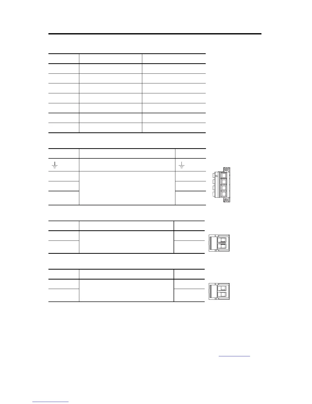
DC-bus Power Supply Connectors
Mains Input Power (IPD) Connector Pinout
Shunt Power (RC) Connector Pinout
Contactor Enable (CED) Connector Pinout
The contactor-enable circuitry includes a relay-driven contact within the 2198-Pxxx DC-bus
power supply. The relay protects the Kinetix 5700 drive system in the event of overloads or other
fault conditions.
An AC three-phase mains contactor must be wired in series between the branch circuit
protection and the DC-bus power supply. In addition, the AC three-phase contactor control
string must be wired in series with the contactor-enable relay at the contactor enable (CED)
connector. Refer to the Kinetix 5700 Servo Drives User Manual, publication 2198-UM002
, for
wiring examples.
Designator Description Connector
IPD AC mains input power 4-position plug, terminal screws
DC DC common bus power DC-bus links and end caps
CP 24V control input power 2-position plug, terminal screws
RC Shunt power 2-position plug, terminal screws
IOD Digital inputs 4-position plug, spring terminals
CED Contactor enable 2-position plug, terminal screws
PORT1, PORT2 Ethernet communication ports RJ45 Ethernet
IPD Pin Description Signal
Chassis ground
L3
Three-phase input power
L3
L2 L2
L1 L1
RC Pin Description Signal
1
Shunt connections
SH
2DC+
CED Pin Description Signal
EN–
Contactor-enable connections
CONT EN–
EN+ CONT EN+
 Loading...


