Kinetix 5700 DC-bus Power Supplies 11
Rockwell Automation Publication 2198-IN009B-EN-P - June 2015
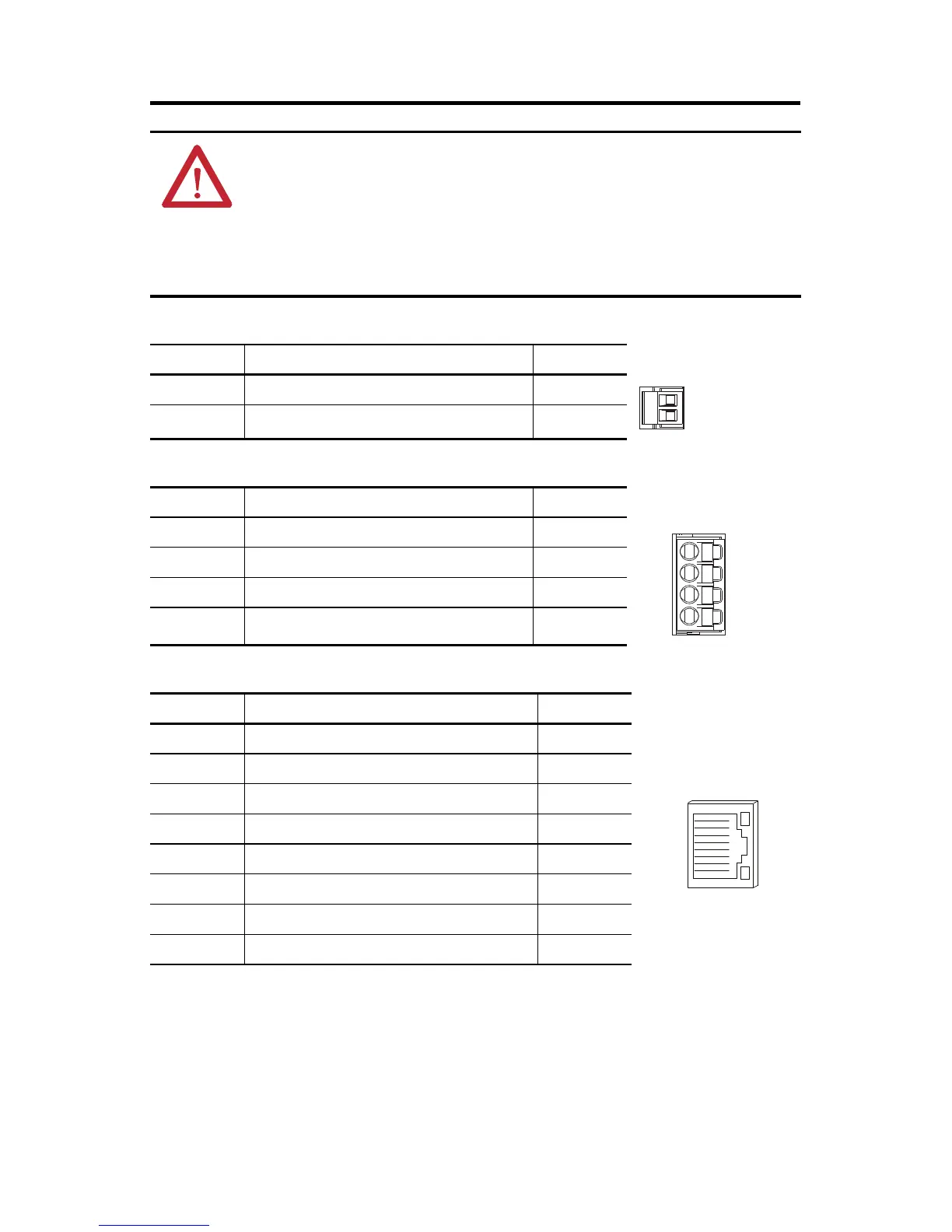
Control Input Power (CP) Connector Pinout
Digital Inputs (IOD) Connector Pinout
Ethernet Communication PORT1 and PORT2 Pinout
ATTENTION: Wiring the contactor-enable relay is required. To avoid personal injury or damage to
the Kinetix 5700 drive system, wire the contactor-enable relay into your control string so that:
• three-phase power is removed and the DC-bus power supply is protected under various fault
conditions.
• three-phase power is never applied to the Kinetix 5700 drive system before control power is
applied.
CP Pin Description Signal
224V common 24V-
1 24V power supply, customer-supplied 24V+
IOD Pin Description Signal
1 Digital input #1 IN1
2 I/O common for customer-supplied 24V supply. COM
3 Digital input #2 IN2
4 I/O cable shield termination point. SHLD
Port Pin Description Signal
1 Transmit port (+) data terminal + TX
2 Transmit port (-) data terminal - TX
3 Receive port (+) data terminal + RX
4– –
5– –
6 Receive port (-) data terminal - RX
7– –
8– –
 Loading...


