166 Rockwell Automation Publication 2198-UM002G-EN-P - February 2019
Chapter 5 Connect the Kinetix 5700 Drive System
Include a new 12 mm (0.5 in.) section of cable jacket and slide it down
to the end of the shield braid.
3. Apply heat shrink to the small section of cable jacket.
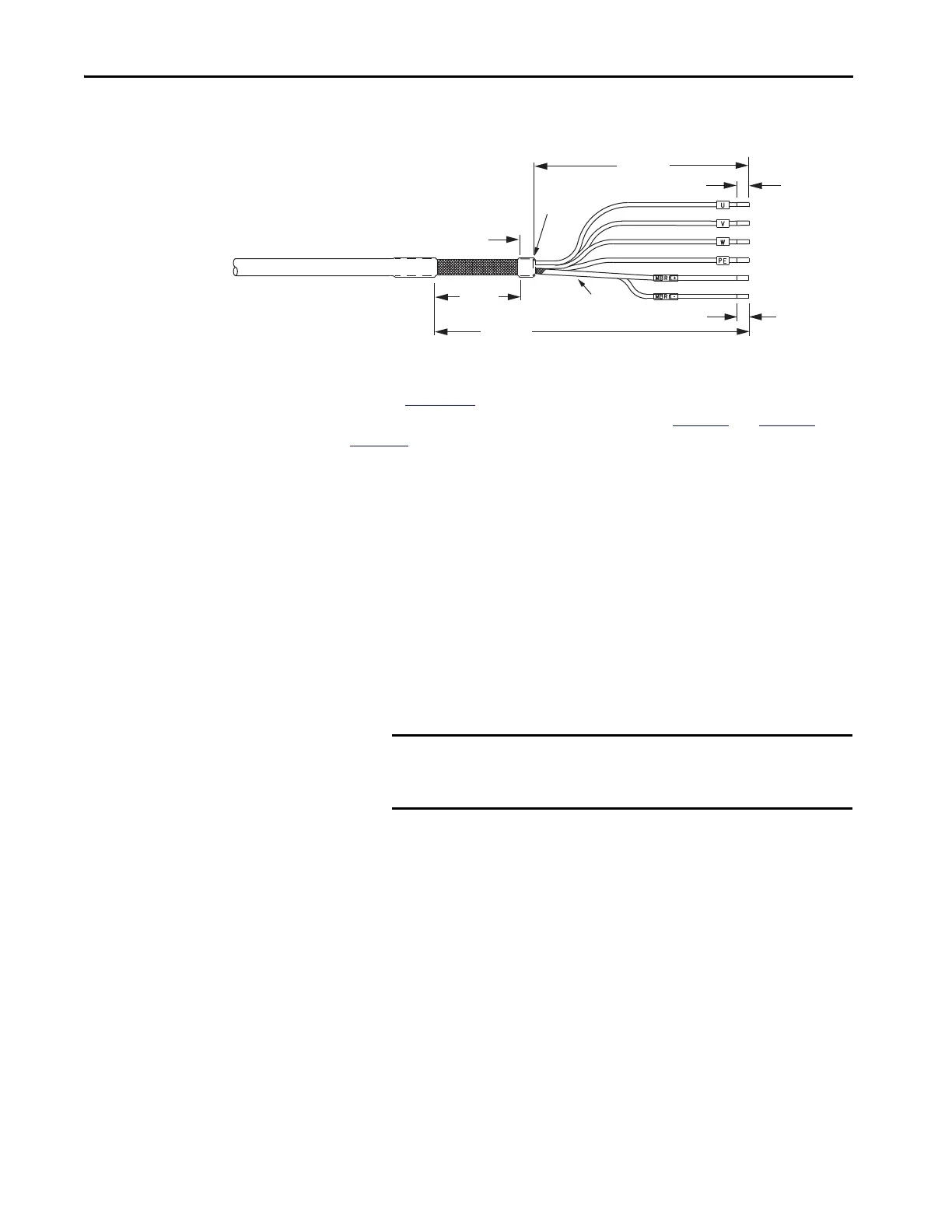
Refer to Figure 111
for typical installation examples for series A and series B
cables. For strip lengths and torque values, refer to Tab l e 7 5
and Tabl e 76 on
page 153
.
Dual-axis Inverter Shield Clamp Installation
Follow these steps to apply the dual-axis inverter cable shield clamp.
1. Loosen the clamp knob and determine if you need the clamp spacers.
The power/brake cable shield attaches to the dual-axis inverter cable
clamp. Clamp spacers are included with the dual-axis inverters for cable
diameters that are too small for a tight fit within the drive clamp alone.
The spacers are held captive by nylon rivets. Remove the rivets and
spacers when your cable shield is of sufficient diameter for the clamp to
hold the cable secure.
2. Position the exposed portion of each cable braid directly in line with the
clamp.
3. Hand tighten the clamp knob.
Make sure the cable clamp tightens around the cable shield and provides
a good bond between the cable shield and the drive chassis.
7.0 (0.28)
305 (12)
221 (8.7)
10.0 (0.39)
12 (0.50)
71 (2.8)
Dimensions are in mm (in.)
Power Conductors
Brake
Conductors
MP-Series Motors
and Actuators
Brake Shield
(trimmed back)
Edge of
Cable Jacket
IMPORTANT Most 2090-CPxM7DF power/brake cables require the spacers.
Only 10 AWG cables with brake conductors have a diameter
large enough to fit in the clamp without the spacers.

 Loading...


