Rockwell Automation Publication 2198-UM002G-EN-P - February 2019 27
Start Chapter 1
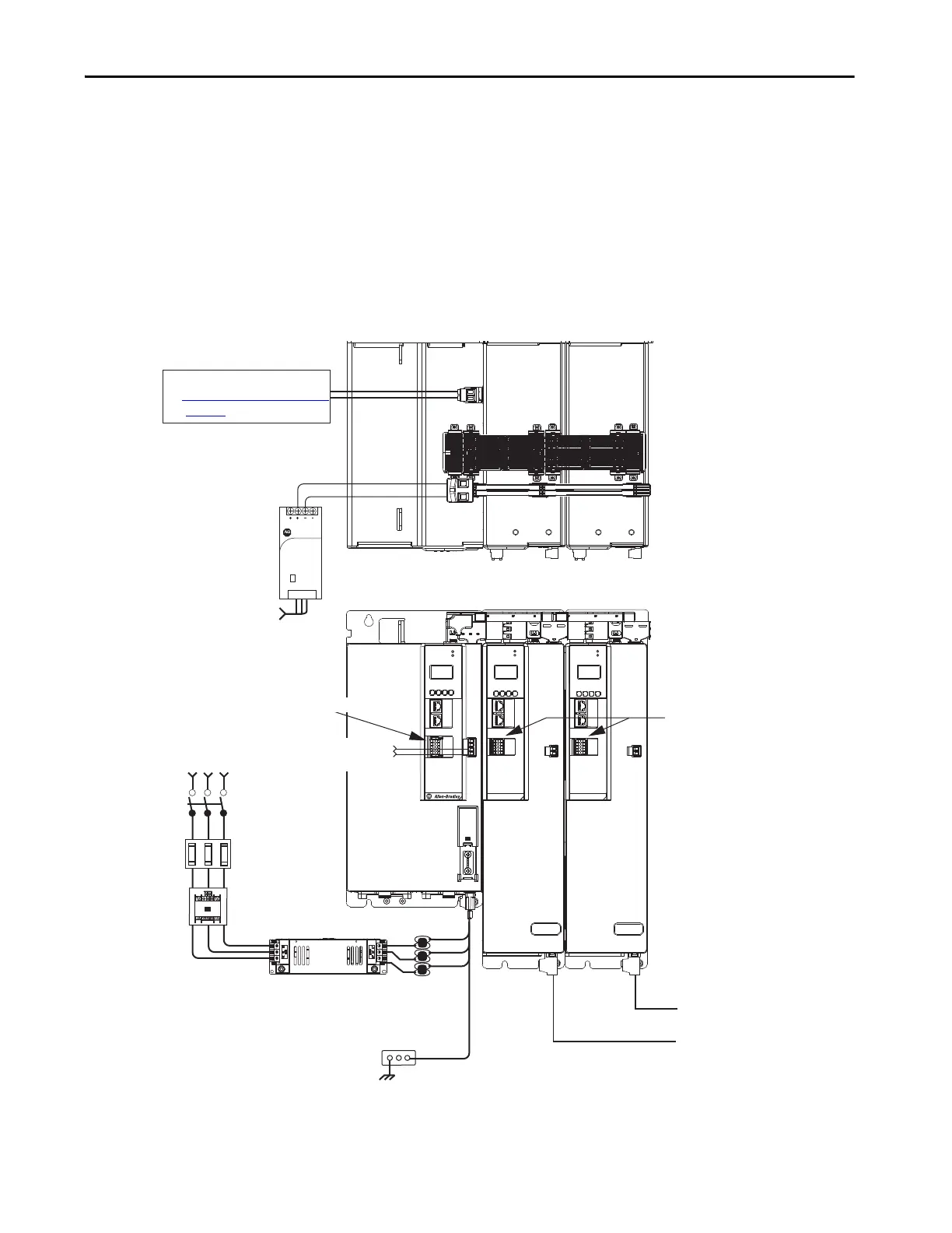
iTRAK Power Supply Configuration Example
In this example, AC input power is fed to the regenerative bus supply. Two
iTRAK power supplies support up to 40 iTRAK motor modules, depending
on cable lengths and iTRAK motor-module power consumption.
Digital inputs are wired to sensors and the control circuitry at the IOD
connectors. The contactor-enable relay protects the regenerative bus supply in
the event of shutdown fault conditions.
Figure 9 - Typical iTRAK Power Supply Installation
2
1
16
I/O
510
–
iPS RDY
+
MOD–
NET–
1
2
3
4
5
6
7
8
9
10
2
1
16
I/O
510
–
iPS RDY
+
MOD–
NET–
1
2
3
4
5
6
7
8
9
10
1606-XL
Power Supply
Input
Allen-Bradley
DC+
MOD
NET
2
1
1
I/O
6
5
10
OK+
OK–
EN–
EN+
DC–
Magnetic Contactor
(M1) Control String
1606-XLxxx
24V DC Control, Digital Inputs,
and iTRAK Motor Module Control Power
(customer-supplied)
AC Input Power
Kinetix 5700 iTRAK System
(front view)
Kinetix 5700 iTRAK System
(top view)
Line Disconnect
Device
324…506V AC
Three-phase
Input Power
Circuit
Protection
Magnetic (M1)
Contactor
Bonded Cabinet
Ground Bus
Converter Digital Inputs
iTRAK Motor Modules
Regenerative Bus Supply
iTRAK
Power Supply
iTRAK
Power Supply
iTRAK Motor Modules
iTRAK Power Supply
Digital Inputs
Bulletin 2198 shared-bus
connection system for DC-bus and
24V DC control power.
Shared DC-bus Power Input
Shared 24V Control Power Input
(24V shared-bus connection system
is optional)
2198T-CHBFLS8
Motor Power
Cables
Active Shunt (optional component)
See External Active-shunt Connections
on page 183
for more information.
Bulletin 1321
Line Reactor
(recommended)
2198-DBRxx-F
AC Line Filter
(can be required for CE)

 Loading...


