Rockwell Automation Publication 2198-UM002G-EN-P - February 2019 205
Configure and Start the Kinetix 5700 Drive System Chapter 6
6. From the pull-down menus, choose the power options appropriate for
your hardware configuration.
7. Click OK to close the New Module dialog box.
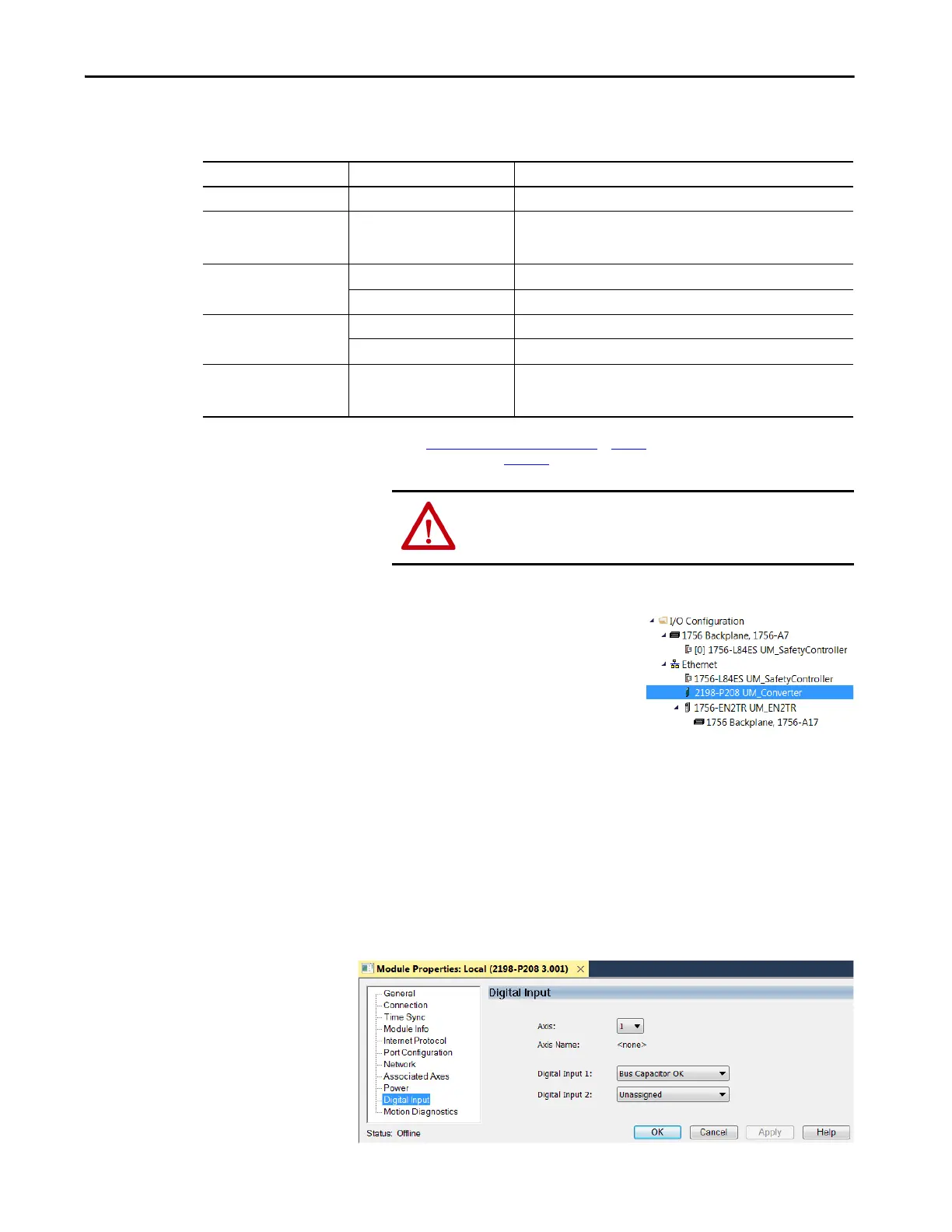
8. Your 2198-Pxxx DC-bus power
supply appears in the Controller
Organizer under the Ethernet
network in the I/O Configuration
folder.
9. Click Close to close the Select Module Type dialog box.
10. Right-click the DC-bus power supply you just created in the Controller
Organizer and choose Properties.
The Module Properties dialog box appears.
11. Click the Digital Input category.
Attribute Menu Description
Bus Configuration Shared AC/DC
(1)
Applies to 2198-Pxxx DC-bus power supply (converter) modules.
Bus Sharing Group
(2)
•Group1
•Group2
•Group3…
Applies to any bus-sharing configuration.
Bus Regulator Action
Disabled Disables the internal shunt resistor and external shunt option.
Shunt Regulator Enables the internal and external shunt options.
Shunt Regulator Resistor Type
Internal Enables the internal shunt (external shunt option is disabled).
External Enables the external shunt (internal shunt option is disabled).
External Shunt
(3)
•None
• 2198-R004, 2198-R014
• 2198-R031, 2198-R127
Selects external shunt option. Only the shunt catalog number intended for
the specific DC-bus power supply is shown.
(1) Shared AC/DC bus configuration is the default selection for DC-bus power supplies.
(2) For more information on bus-sharing groups, refer to Understand Bus-sharing Group Configuration
on page 263.
(3) Refer to the Kinetix Servo Drives Specifications Technical Data, publication KNX-TD003
, for more information on the Bulletin 2198 external passive shunt resistors.
ATTENTION: To avoid damage to equipment all modules physically
connected to the same shared-bus connection system must be part
of the same Bus Sharing Group in the Logix Designer application.
TIP To configure the remaining DC-bus power supply properties, you
must close the New Module dialog box and reopen it as the Module
Properties dialog box.

 Loading...


