Rockwell Automation Publication 2198-UM002G-EN-P - February 2019 327
Kinetix 5700 Safe Torque-off Function Chapter 9
Table 166 - Dual-axis Inverter Integrated STO Specifications
In these examples, the appropriate STO bit permits torque when the bit is high
(see Table 164
on page 326 for changes in STO tag names).
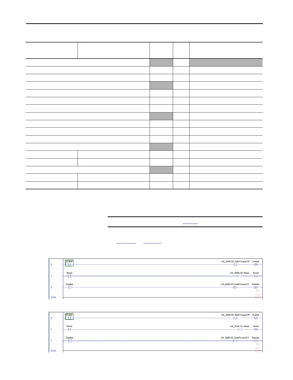
Figure 153 - STO Function (Logix Designer, version 30 or earlier)
Figure 154 - STO Function with STO Only (Logix Designer, version 31 or later)
Logix Designer Tag Name
Safe Stop Only - No Feedback Tag Names
Studio 5000 Logix Designer
(version 31 and later)
Attribute
[bit]
Type Description
SI.ConnectionStatus
(1)
(2)
DINT
SI.RunMode [0] BOOL Combinations of the RunMode and
SI.ConnectionFaulted [1] BOOL ConnectionFaulted states
SI.Status1
(1)
(3)
SINT Motion Safety 1
SI.TorqueDisabled1 [0] BOOL 0 = Torque Permitted; 1 = Torque Disabled
SI.SafetyFault1 [6] BOOL 1 = STO Fault present
SI.ResetRequired1 [7] BOOL 1 = A reset is required
SI.Status2
(1)
(3)
SINT Motion Safety 2
SI.TorqueDisabled2 [0] BOOL 0 = Torque Permitted; 1 = Torque Disabled
SI.SafetyFault2 [6] BOOL 1 = STO Fault present
SI.ResetRequired2 [7] BOOL 1 = A reset is required
SO.Command1
(1)
(4)
SINT Motion Safety 1
SO.SafeTorqueOff1 SO.STOOutput1 [0] BOOL 0 = Disable Permit; 1 = Permit Torque
SO.Reset1 SO.ResetRequest1 [7] BOOL 0-->1 = Reset STO Fault
SO.Command2
(1)
(4)
SINT Motion Safety 2
SO.SafeTorqueOff2 SO.STOOutput2 [0] BOOL 0 = Disable Permit; 1 = Permit Torque
SO.Reset2 SO.ResetRequest2 [7] BOOL 0-->1 = Reset STO Fault
(1) Bits not listed are always zero.
(2) ConnectionStatus is determined by the Safety Validator in the GuardLogix controller.
(3) Status is sent from the drive to the controller using integrated safety protocol.
(4) The Command is sent from the controller to the drive using integrated safety protocol.
IMPORTANT Only the data listed in Table 166 is communicated with SIL 3 integrity.

 Loading...


