242 Rockwell Automation Publication 750-IN001O-EN-P - October 2014
Chapter 5 I/O Wiring
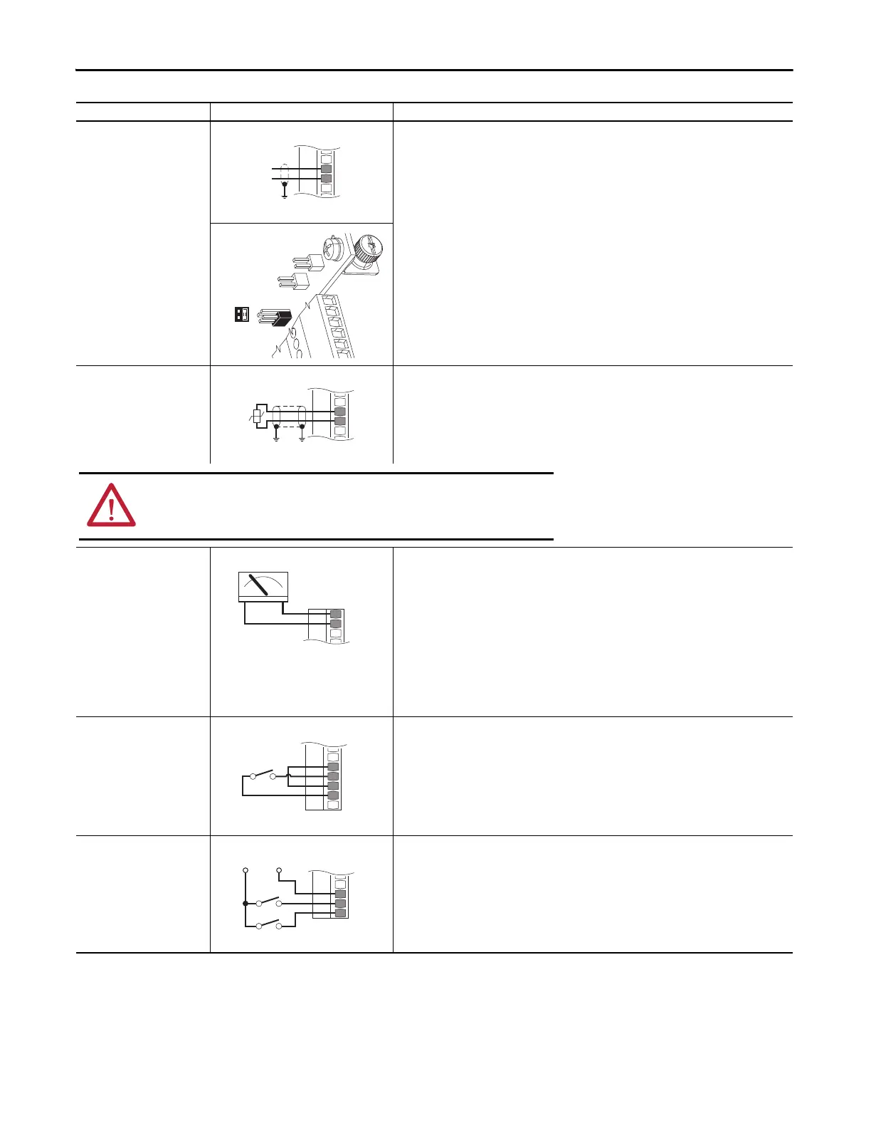
Analog Current Input
Unipolar Speed Reference
0-20 mA Input
753 Main Control Board TB1
• Set Direction Mode
Port 0: P308 [Direction Mode] = 0 “Unipolar”
• Set Selection
Port 0: P545 [Spd Ref A Sel] = Port 0: P260 [Anlg In0 Value]
• Adjust Scaling
Port 0: P261 [Anlg In0 Hi] = 20 mA
Port 0: P262 [Anlg In0 Lo] = 0 mA
Port 0: P547 [Spd Ref A AnlgHi] = 60 Hz
Port 0: P548 [Spd Ref A AnlgLo] = 0 Hz
• View Results
Port 0: P260 [Anlg In0 Value]
Port 0: P592 [Selected Spd Ref]
HW Input PTC
Standard = No design standard
PTC Nominal = 1.8 k Ohm
PTC Trip = 3.1 k Ohm
PTC Reset = 2.2 k Ohm
Short Circuit Trip - No fault
753 Main Control Board TB1
• Configuration
Port 0: P250 [PTC Cfg] = 0 “Ignore,” 1 “Alarm,” 2 “Flt Minor,”
3 “FltCoastStop,” 4 “Flt RampStop,” or 5 “Flt CL Stop”
• View Results
Port 0: P251 [PTC Status]
Analog Voltage Output
±10V, 0…20 mA Bipolar
+10V Unipolar
753 Main Control Board TB1
• Configuration
Port 0: P270 [Anlg Out Type], bit 0 = 0
• Set Selection
Port 0: P275 [Anlg Out0 Sel] = Port 0: P3 [Mtr Vel Fdbk]
• Adjust Scaling
Port 0: P278 [Anlg Out0 DataHi] = 60 Hz
Port 0: P279 [Anlg Out0 DataLo] = 0 Hz
Port 0: P280 [Anlg Out0 Hi] =10V/20 mA
Port 0: P281 [Anlg Out0 Lo] = 0V/0 mA
• View Results
Port 0: P277 [Anlg Out0 Data]
Port 0: P282 [Anlg Out0 Val]
2-Wire Control Non-
Reversing
24V DC internal supply
753 Main Control Board TB1
• Set Direction Mode
Port 0: P308 [Direction Mode] = 2 “Rev Disable”
• Set Selection
Port 0: P163 [DI Run] = Port 0: P220 [Digital In Sts], bit 1 = Digital In 1
• View Results
Port 0: P220 [Digital In Sts]
Port 0: P935 [Drive Status 1]
2-Wire Control Reversing
External 24 volt supply
753 Main Control Board TB1
• Set Direction Mode
Port 0: P308 [Direction Mode] = 0 “Unipolar”
• Set Selection
Port 0: P164 [DI Run Forward] = Port 0: P220 [Digital In Sts], bit 1 = Digital In 1
Port 0: P165 [DI Run Reverse] = Port 0: P220 [Digital In Sts], bit 2 = Digital In 2
• View Results
Port 0: P220 [Digital In Sts]
Port 0: P935 [Drive Status 1]
Input/Output Connection Example Required Parameter Changes
Ai0–
Ai0+
Common
+
J4
3 1
4 2
1.8k
PTC
Ptc–
Ptc+
ATTENTION: To avoid an electric shock hazard, the connection of the motor
temperature sensor requires double or reinforced insulation between motor live
parts and the PTC.
Ao0–
Ao0+
+–
Di C
Di 1
Di 2
+24V Common
Run Fwd
Run Rev
 Loading...


