120 Rockwell Automation Publication 520-UM001A-EN-E - February 2013
Chapter 3 Programming and Parameters
Fault and Diagnostic Group (continued)
F641 [Fault 1 Current]
F643 [Fault 3 Current]
F645 [Fault 5 Current]
F647 [Fault 7 Current]
F649 [Fault 9 Current]
F642 [Fault 2 Current] Related Parameter(s): b003
F644 [Fault 4 Current]
F646 [Fault 6 Current]
F648 [Fault 8 Current]
F650 [Fault10 Current]
Displays and stores the value of b003
[Output Current] with the most recent 10 faults occurred.
[Fault 1 Current] stores the most recent fault, [Fault 2 Current] stores the second most recent fault and [Fault 3 Current] stores the third most recent fault.
Values Default: Read Only
Min/Max: 0.00/(Drive Rated Amps x 2)
Display: 0.01 A
F651 [Fault 1 BusVolts]
F653 [Fault 3 BusVolts]
F655 [Fault 5 BusVolts]
F657 [Fault 7 BusVolts]
F659 [Fault 9 BusVolts]
F652 [Fault 2 BusVolts] Related Parameter(s): b005
F654 [Fault 4 BusVolts]
F656 [Fault 6 BusVolts]
F658 [Fault 8 BusVolts]
F660 [Fault10 BusVolts]
Displays and stores the value of b005
[DC Bus Voltage] with the most recent 10 faults occurred.
[Fault 1 BusVolts] stores the most recent fault, [Fault2 BusVolts] stores the second most recent fault and [Fault 3 BusVolts] stores the third most recent fault.
Values Default: Read Only
Min/Max: 0/Based on Drive Rating
Display: 1V DC
F661 [Status @ Fault 1]
F663 [Status @ Fault 3]
F665 [Status @ Fault 5]
F667 [Status @ Fault 7]
F669 [Status @ Fault 9]
F662 [Status @ Fault 2] Related Parameter(s): b006
F664 [Status @ Fault 4]
F666 [Status @ Fault 6]
F668 [Status @ Fault 8]
F670 [Status @ Fault10]
Displays the value of b006
[Drive Status] with the most recent 10 faults occurred.
[Status@ Fault 1] stores the most recent fault, [Status@ Fault 2] stores the second most recent fault and [Status@ Fault 3] stores the third most recent fault.
Values Default: Read Only
Min/Max: 0/0x1F
Display: 1
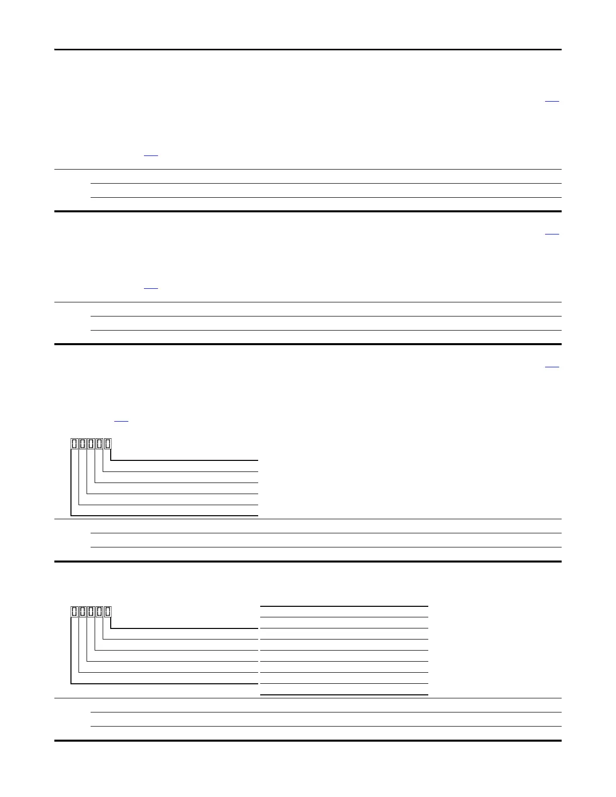
1 = Condition True, 0 = Condition False
Running Digit 1
Forward Digit 2
Accelerating Digit 3
Decelerating Digit 4
SafetyActive Digit 5
F681 [Comm Sts - DSI]
Displays the status of the RS485 serial (DSI) port to the drive.
Values Default: Read Only
Min/Max: 0000/1911
Display: 0000
1 = Condition True, 0 = Condition False
Rx Digit 1
Tx Digit 2
Status Digit 3
Error Digit 4
Not Used
Digit 3 (Connection Status)
0 “Not Active”
1 “Modbus slave network (external Modbus master)”
2 “Modbus multi-drive w/ internal com option master”
3 “Modbus multi-drive w/ embedded com master”
4 “DSI peripheral connected”
5...8 “Reserved”
9 “RS-485 network faulted”
 Loading...


