134 Rockwell Automation Publication 520-UM001A-EN-E - February 2013
Chapter 4 Troubleshooting
Fault Indication
Manually Clearing Faults
Automatically Clearing Faults
Condition Display
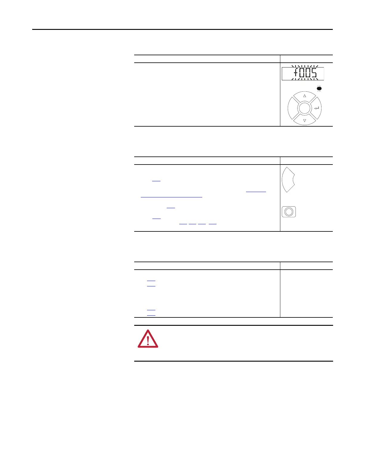
Drive is indicating a fault.
The integral LCD display provides visual notification of a fault condition by displaying the
following.
• Flashing fault number
• Flashing fault indicator (LED)
Press the Esc key to regain control of the display.
Step Key(s)
1. Press Esc to acknowledge the fault. The fault information will be removed so that you
can use the integral keypad.
Access b007
[Fault 1 Code] to view the most recent fault information.
2. Address the condition that caused the fault.
The cause must be corrected before the fault can be cleared. See Fault Types,
Descriptions and Actions on page 135.
3. After corrective action has been taken, clear the fault by one of these methods.
• Press Stop if P045 [Stop Mode] is set to a value between “0” and “3”.
• Cycle drive power.
• Set A551 [Fault Clear] to 1 “Reset Fault” or 2 “Clear Buffer”.
• Cycle digital input if t062, t063, t065...t068 [DigIn TermBlk xx] is set to
13 “Clear Fault”.
Option/Step
Clear a Type 1 fault and restart the drive.
1. Set A541 [Auto Rstrt Tries] to a value other than “0”.
2. Set A542 [Auto Rstrt Delay] to a value other than “0”.
Clear an OverVoltage, UnderVoltage or Heatsink OvrTmp fault
without restarting the drive.
1. Set A541 [Auto Rstrt Tries] to a value other than “0”.
2. Set A542 [Auto Rstrt Delay] to “0”.
ATTENTION: Equipment damage and/or personal injury may result if these
parameters are used in an inappropriate application. Do not use this function
without considering applicable local, national and international codes,
standards, regulations or industry guidelines.

 Loading...


