Rockwell Automation Publication 520-UM001A-EN-E - February 2013 45
Installation/Wiring Chapter 1
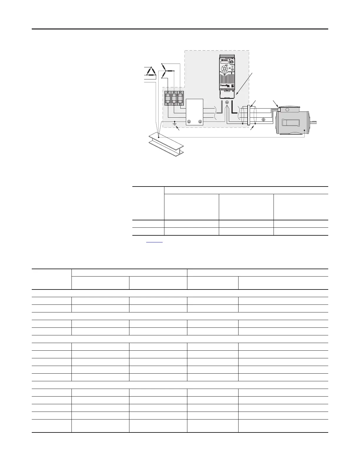
Connections and Grounding
(1) Some installations require a shielded enclosure. Keep wire length as short as possible between the enclosure entry point and the
EMI filter.
PowerFlex 525 RF Emission Compliance and Installation Requirements
Filter Type Standard/Limits
EN61800-3 Category C1
EN61000-6-3
CISPR11 Group 1 Class B
EN61800-3 Category C2
EN61000-6-4
CISPR11 Group 1 Class A
(Input power ≤ 20 kVA)
EN61800-3 Category C3
(I ≤ 100 A)
CISPR11 Group 1 Class A
(Input power > 20 kVA)
Internal – 10 m (33 ft) 20 m (66 ft)
External
(1)
(1) See Appendix B for more information on optional external filters.
30 m (16 ft) 100 m (328 ft) 100 m (328 ft)
R/L1
S/L2
T/L3
U/T1
V/T2
W/T3
EMI ttings and metal conduit
IP 30/NEMA 1/UL Type 1
option kit or EMC kit
Shielded enclosure
(1)
Building structure steel
Enclosure ground connection
EMI lter
L1'
L2'
L3'
L1
L2
L3
Shielded motor cable
Additional Installation Requirements
Frame Size Class C1 Class C2
Enclosure and Conduit Cable
(Input and Output)
EMC Cores Required
(1)
Enclosure EMC Cores Required
(1)
200...240V AC (-15%, +10%) – 1-Phase Input with External EMC Filter, 0...230V 3-Phase Output
A Shielded None None INPUT (CORE-RF-A-1) / OUTPUT (CORE-RF-A-2)
B Shielded OUTPUT (CORE-RF-B-2) None INPUT (CORE-RF-B-1) / OUTPUT (CORE-RF-B-2)
200...240V AC (-15%, +10%) – 1-Phase Input with Internal EMC Filter, 0...230V 3-Phase Output
A– – ShieldedNone
B– – ShieldedNone
200...240V AC (-15%, +10%) – 3-Phase Input with External EMC Filter, 0...230V 3-Phase Output
A Shielded OUTPUT (CORE-RF-A-2) None INPUT (CORE-RF-A-1) / OUTPUT (CORE-RF-A-2)
B Shielded OUTPUT (CORE-RF-B-2) None INPUT (CORE-RF-B-1) / OUTPUT (CORE-RF-B-2)
C Shielded OUTPUT (CORE-RF-C-2) None INPUT (CORE-RF-C-1) / OUTPUT (CORE-RF-C-2)
D Shielded None None INPUT (CORE-RF-D-1)
E Shielded None None INPUT (CORE-RF-E-1)
380...480V AC (-15%, +10%) – 3-Phase Input with External EMC Filter, 0...460V 3-Phase Output
A Shielded None None INPUT (CORE-RF-A-1) / OUTPUT (CORE-RF-A-2)
B Shielded None None INPUT (CORE-RF-B-1) / OUTPUT (CORE-RF-B-2)
C Shielded None None INPUT (CORE-RF-C-1)
D Shielded OUTPUT (CORE-RF-D-2) None INPUT (CORE-RF-D-1) / OUTPUT (CORE-RF-D-2)
E Shielded None Shielded INPUT -1 (CORE-E-1) and INPUT-2 (CORE-E-2) /
OUTPUT-1 (CORE-E-3) and OUTPUT-2 (CORE-E-4)
 Loading...


