46 Rockwell Automation Publication 520-UM001A-EN-E - February 2013
Chapter 1 Installation/Wiring
380...480V AC (-15%, +10%) – 3-Phase Input with Internal EMC Filter, 0...460V 3-Phase Output
A – – None INPUT (CORE-A-1) / OUTPUT (CORE-A-2)
B – – None INPUT (CORE-B-1) / OUTPUT (CORE-B-2)
C – – None INPUT (CORE-C-1) / OUTPUT (CORE-C-2)
D – – None INPUT (CORE-D-1) / OUTPUT (CORE-D-2)
E – – None INPUT -1 (CORE-E-1) and INPUT-2 (CORE-E-2) /
OUTPUT-1 (CORE-E-3) and OUTPUT-2 (CORE-E-4)
525...600V AC (-15%, +10%) – 3-Phase Input with External EMC Filter, 0...575V 3-Phase Output
A Shielded None None INPUT (CORE-RF-B-1) / OUTPUT (CORE-RF-B-2)
B Shielded None None INPUT (CORE-RF-B-1) / OUTPUT (CORE-RF-B-2)
C Shielded None None INPUT (CORE-RF-C-1) / OUTPUT (CORE-RF-C-2)
D Shielded None None INPUT (CORE-RF-D-1) / OUTPUT (CORE-RF-D-2)
E Shielded None Shielded None
(1) EMC cores are included with product.
Additional Installation Requirements
Frame Size Class C1 Class C2
Enclosure and Conduit Cable
(Input and Output)
EMC Cores Required
(1)
Enclosure EMC Cores Required
(1)
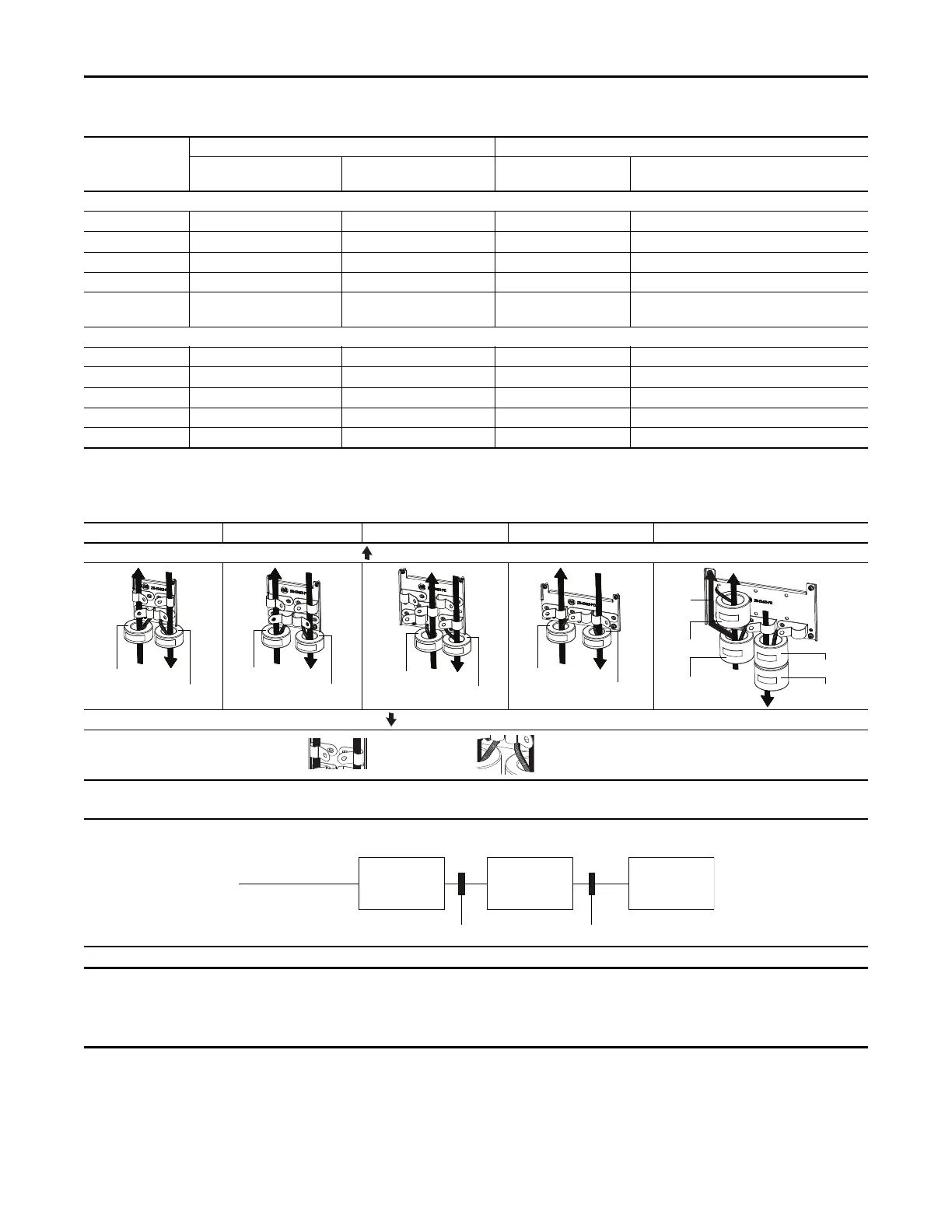
Recommended Placement of EMC Cores with EMC Plate
Frame A Frame B Frame C Frame D Frame E
Input cable to drive (Shielded or Unshielded)
Output cable from drive (Shielded)
CORE-INPUT-1
CORE-INPUT-2
CORE-OUTPUT-1
CORE-OUTPUT-2
Ground
cable
Shows contact to
shielded layer
Shows cable/zip tie for
securing EMC Core
Recommended Placement of EMC Cores Relative to External Filter
CORE-INPUT-1/2 CORE-OUTPUT-1/2
Incoming power
EMC Filter Drive Motor
All Frame sizes
The grounded/shielded cable for both input and output must pass through the EMC core(s), except for the following:
• Frame E drives with internal filters where the grounded input cable must only pass through EMC CORE-E-2.
• 600V drives with external filters where the grounded output cable must not pass through the EMC core(s).
 Loading...


