EasyManuals Logo

Allen-Bradley PowerFlex 525 User Manual

Allen-Bradley PowerFlex 525
228 pages
To Next Page IconTo Next Page
To Previous Page IconTo Previous Page
Page #97 background imageLoading...
Page #97 background image
Rockwell Automation Publication 520-UM001A-EN-E - February 2013 97
Programming and Parameters Chapter 3
Advanced Display Group (continued)
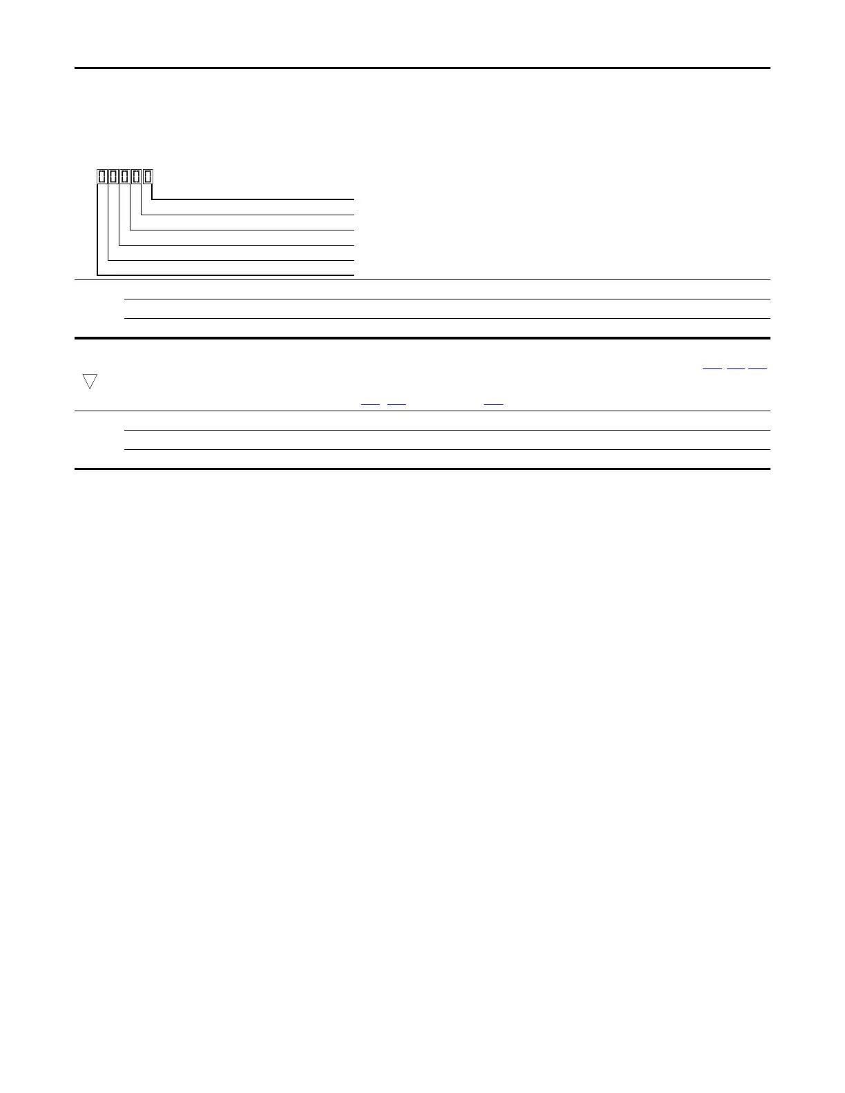
d390 [Fiber Status]
Present status of the Fibers features.
Values Default: Read Only
Min/Max: 0000/1111
Display: 0000
1 = Condition True, 0 = Condition False
Sync Hold Digit 1
Sync Ramp Digit 2
Traverse On Digit 3
Traverse Dec Digit 4
Not Used
d391 [Stp Logic Status] Related Parameter(s): P047, L180-L187
32 bit parameter
Displays the current step of the Step Logic profile as defined by parameters L180...L187 [Step Logic x] when P047 [Speed Reference1] is set to 13 “Step Logic” or 16 “Positioning”.
Values Default: Read Only
Min/Max: 0/8
Display: 1
32

Table of Contents

Other manuals for Allen-Bradley PowerFlex 525

Questions and Answers:

Question and Answer IconNeed help?

Do you have a question about the Allen-Bradley PowerFlex 525 and is the answer not in the manual?

Allen-Bradley PowerFlex 525 Specifications

General IconGeneral
Horsepower0.5-30 HP
kW0.4-22 kW
Input Voltage200-240V AC, 380-480V AC
EnclosureIP20, NEMA/UL Type 1
CommunicationsEtherNet/IP
Control MethodsV/Hz, Sensorless Vector
STOSafe Torque Off (STO)
Output Voltage0-Input Voltage
Operating Temperature-20°C to 50°C (-4°F to 122°F)
Storage Temperature-40°C to 85°C (-40°F to 185°F)
Relative Humidity5-95% non-condensing
DimensionsVaries by model
WeightVaries by model

Related product manuals