EasyManuals Logo
Home>Allen-Bradley>DC Drives>PowerFlex 6000

Allen-Bradley PowerFlex 6000 Installation Instructions

Allen-Bradley PowerFlex 6000
66 pages
To Next Page IconTo Next Page
To Previous Page IconTo Previous Page
Page #12 background imageLoading...
Page #12 background image
12 Rockwell Automation Publication 6000-IN006F-EN-P - March 2018
Chapter 1 Drive Mechanical Installation
3. Secure the cabinets together using M6 or M8 hardware. See To r q u e
Requirements on page 49 for proper torque requirements.
Open the doors to access front edge joining holes (four or five places).
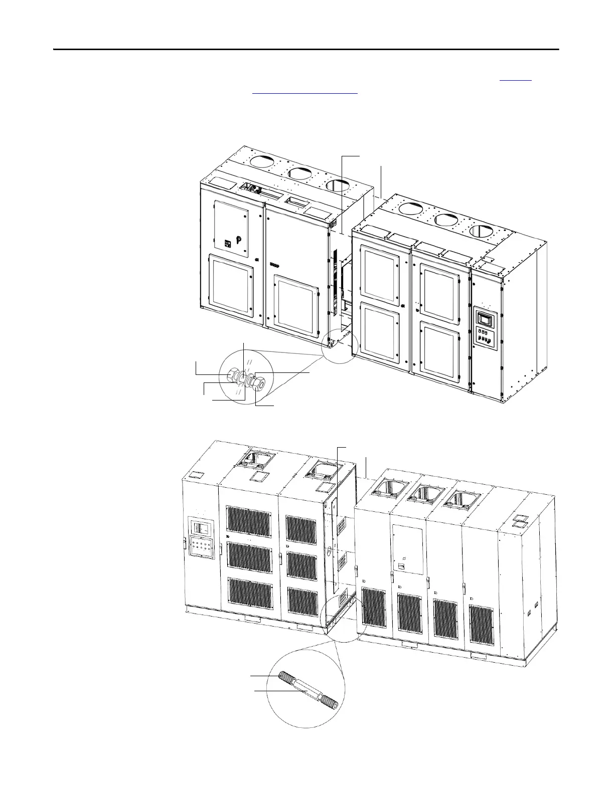
Figure 3 - Secure the Cabinets, Type A
Figure 4 - Secure the Cabinets, Type B
Secure with M8 (or M10)
hardware (10 places)
M10x25 hex bolt
Lock washer
M10 hex nut
Flat washer (x2)
Cabinet sidesheets
Secure with M6
hardware (8 places)
2-socket screw M6x16
Combination pillar

Table of Contents

Other manuals for Allen-Bradley PowerFlex 6000

Questions and Answers:

Question and Answer IconNeed help?

Do you have a question about the Allen-Bradley PowerFlex 6000 and is the answer not in the manual?

Allen-Bradley PowerFlex 6000 Specifications

General IconGeneral
BrandAllen-Bradley
ModelPowerFlex 6000
CategoryDC Drives
LanguageEnglish

Related product manuals