Rockwell Automation Publication 6000-IN006F-EN-P - March 2018 41
Drive Electrical Interconnection Chapter 3
Connect Motor and Voltage
Sensing Board Cables
Introduction
The Voltage Sensing Board cables and the motor cables both connect to the same
output point of each motor phase array (Figure 25
).
The voltage sensing cables needs to be connected on site. For drive ratings with
power modules ≥250 A, the connection points are always on the right side of the
power module cabinet.
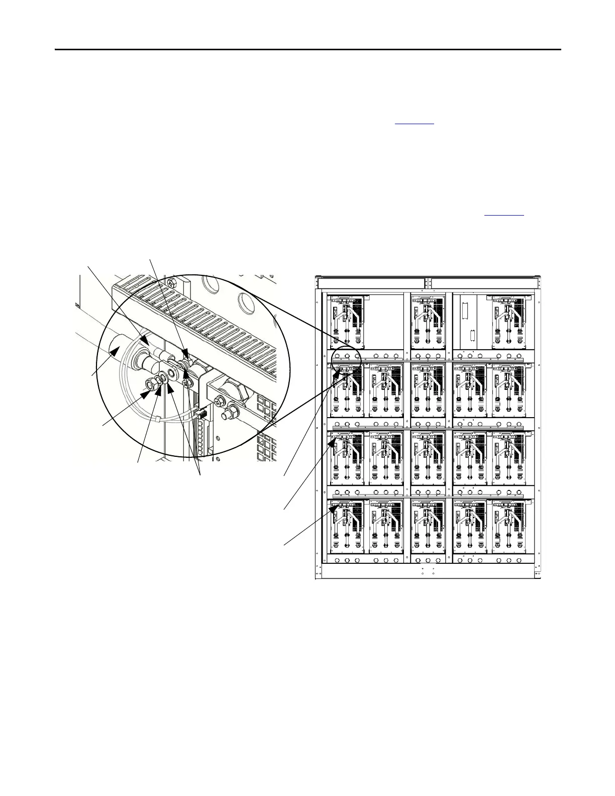
A typical connection with connection points on the left side of the power
module cabinet (for power modules ≤200 A) is shown below (Figure 28
).
Figure 28 - 6.6/6.9 kV Power Module Configuration
Hex nut
Flat washer
Lock washer
Hex bolt
Motor cable
VSB cable
U Phase
V Phase
W Phase
Front View

 Loading...


