Rockwell Automation Publication 6000-IN006F-EN-P - March 2018 13
Drive Mechanical Installation Chapter 1
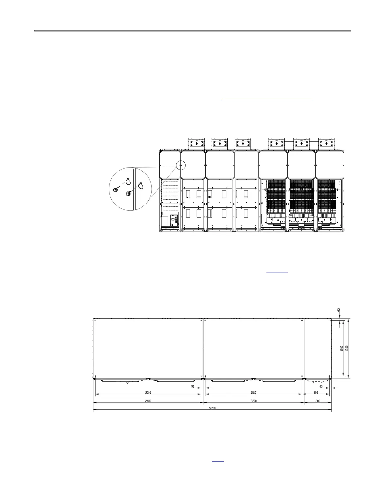
4. Remove all back plates to access rear edge joining holes (five places).
Affix Cabinets to Floor
Typical floor drawings show minimum clearance distance, conduit openings, and
mounting holes for anchor bolts
(1)
, as shown in Figure 5. Refer to customer
specific dimensional drawing for outgoing motor and incoming line cable
openings.
Figure 5 - Typical Floor Drawing, Type A
Secure the cabinet to the channel steel base using M16 bolt, lock washer, two flat
washers and a nut.
Each back plate will have two keyhole screw holes on either side. Remove all of
the other screws first. Loosen the two screws in the keyhole screw holes last
and lift the back plate to remove. Do not remove these screws.
Do not replace the back plates until the Drive Electrical Interconnection Process
is complete (See Drive Electrical Interconnection
on page 37).
To replace the back plates, the two remaining screws orient and hold the back
plate in place while fastening the other screws holding the back plates to the
frame of the cabinet. Tighten these screws last to complete the process.
(1) Mounting holes are represented as + in Figure 5.
Isolation Transformer Cabinet Power Module/LV Control Cabinet
Bottom View

 Loading...


