Rockwell Automation Publication 6000-IN006F-EN-P - March 2018 19
Drive Mechanical Installation Chapter 1
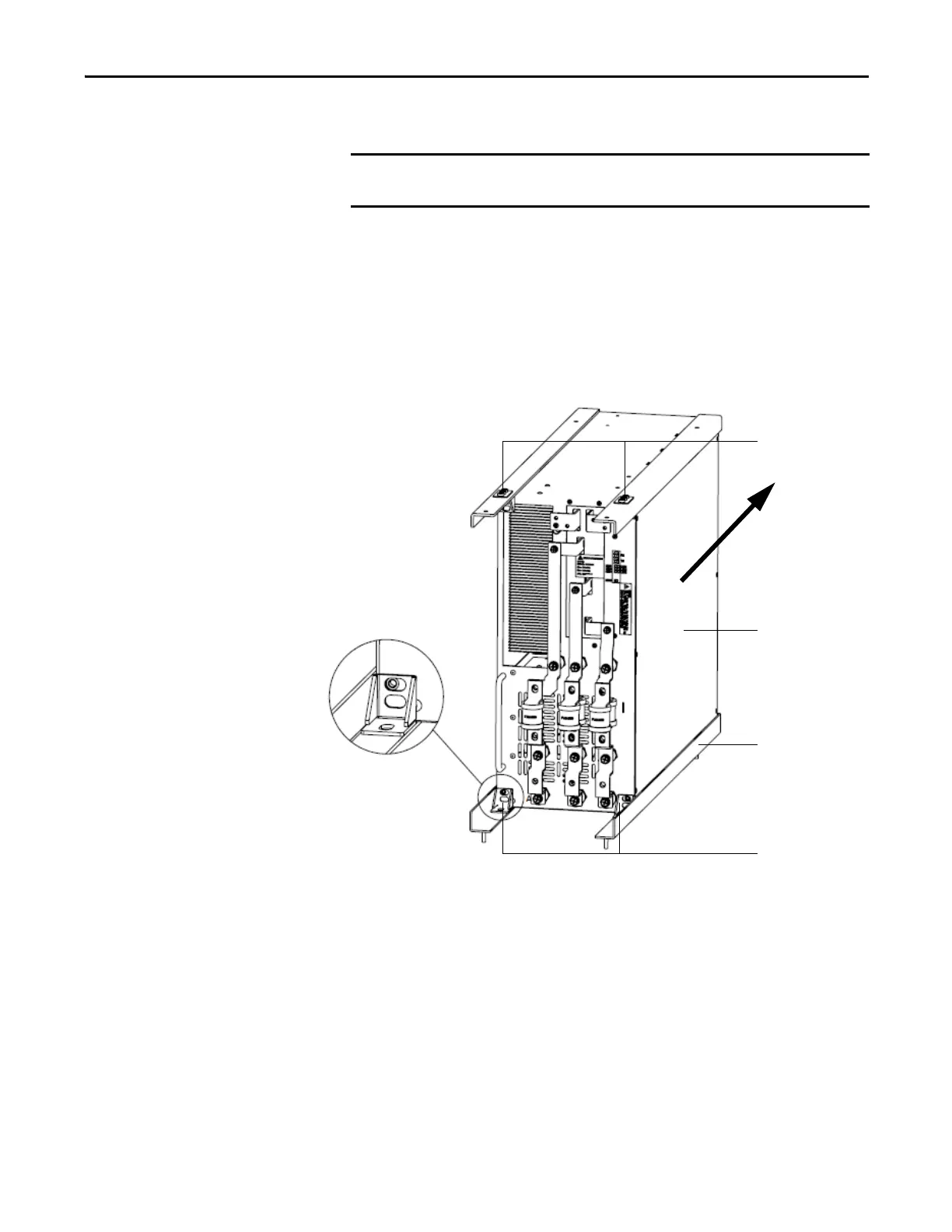
Install Power Modules
1. You can use the lift cart to move and position the Power Module to the
appropriate location in the cabinet.
2. Push the Power Module slowly along the guide rails until it cannot be
pushed in further.
3. After installing the Power Module in place, use the mounting brackets and
the M6 × 16 large flat pad galvanized nickel screws to fix the four corners,
as shown below.
The Power Module should be handled carefully. After removing the packaging,
inspect the Power Module to confirm there is no damage and moisture.
Mounting brackets
Power Module
Guide rail
Mounting brackets

 Loading...


