28 Rockwell Automation Publication 6000-IN006F-EN-P - March 2018
Chapter 2 Drive Electrical Installation
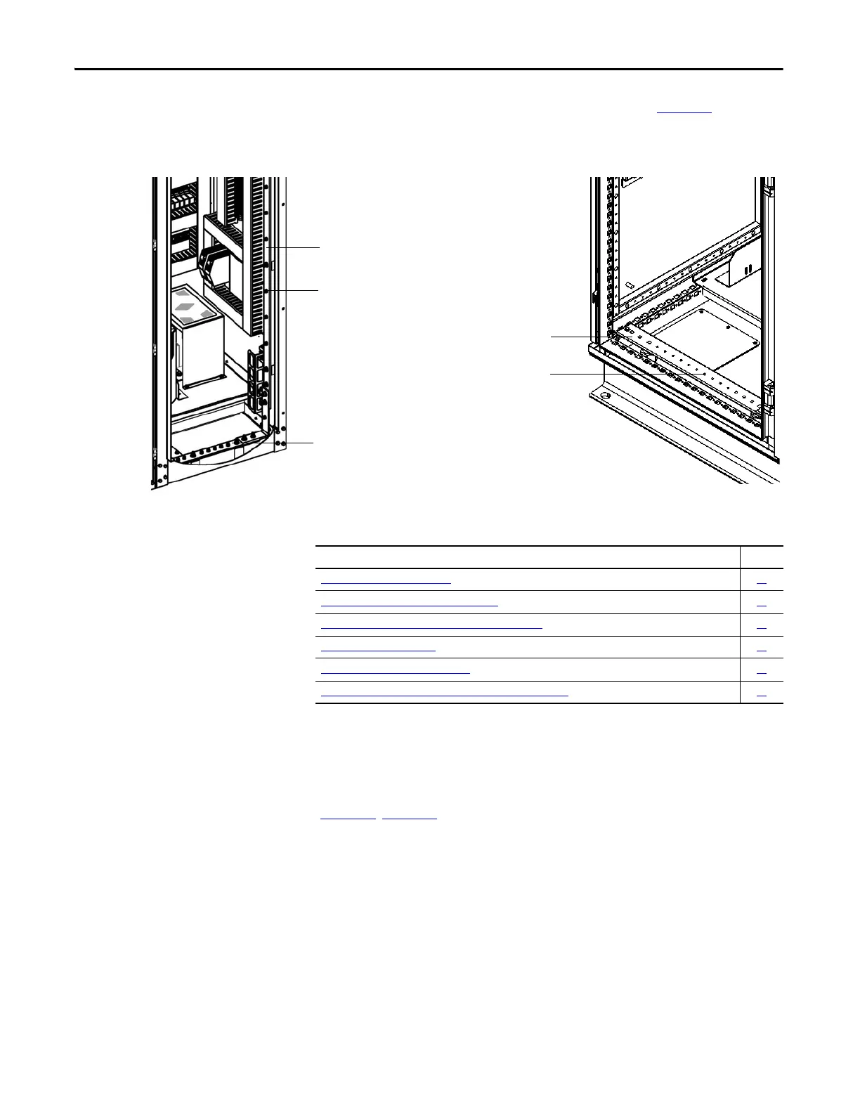
Grounding provisions for control signal wiring is shown in Figure 15.
Figure 15 - Vertical Ground Bus in LV Cabinet
Electrical Installation
Summary
Connect the System Ground
Cable
The drive ground bus runs along the bottom of the drive at the front. The ground
bus is accessible at the bottom of the front of each drive cabinet when the cabinet
door is opened. Connect the system ground cable to the drive ground bus
(Figure 16
, Figure 17).
Vertical Ground Bus
Provisions for Grounding
Control Signal Wiring Shields,
and so on.
Ground Bus
Provisions for Grounding
Control Signal Wiring Shields,
and so on.
Ground Bus
Type A Type B
Connect External Cabling and Wiring Page
Connect the System Ground Cable
28
Insulation Resistance (IR) Test of Power Cables 29
Connect Incoming Line and Outgoing Motor Power Cables 29
Connect Control Power Wiring 32
Connect External Control Signal Wiring 34
Connect Electrical Safety Interlock Circuit to Input Circuit Breaker 35

 Loading...


