14 Rockwell Automation Publication 6000-IN006F-EN-P - March 2018
Chapter 1 Drive Mechanical Installation
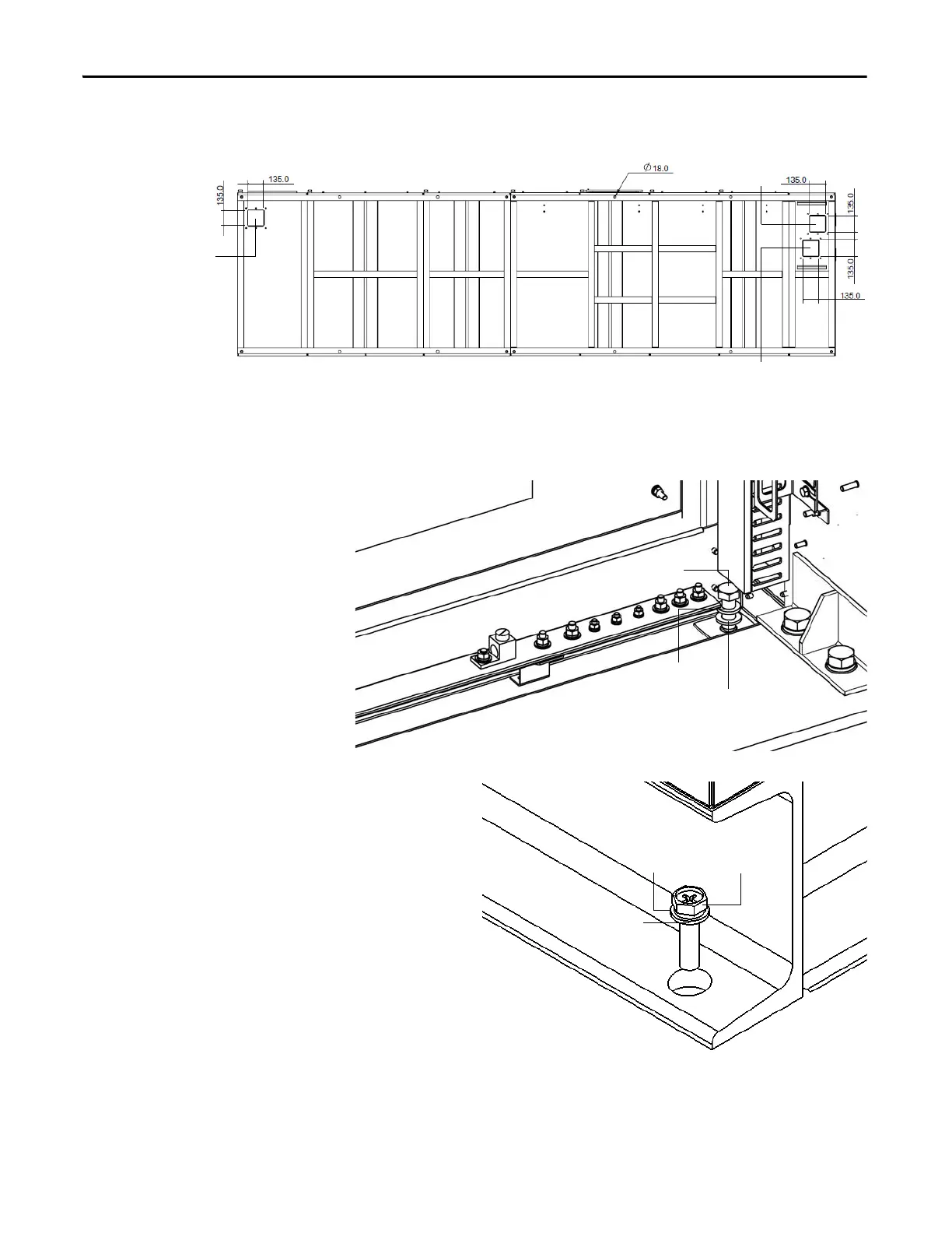
Figure 6 - Typical Floor Drawing, Type B
Secure the cabinet to the channel steel base using M12 bolt (recommended), lock
washer, two flat washers and a nut.
Figure 7 - Bolt Cabinet to Steel Base, Type A
Figure 8 - Bolt Cabinet to Steel Base, Type B
Isolation Transformer CabinetPower Module/LV Control Cabinet
Bottom View
Control signal
Output cable
Input cable
M16 bolt
Flat washer
Lock washer
M16 bolt
Flat washer
Lock washer
 Loading...


