Rockwell Automation Publication 6000-IN006F-EN-P - March 2018 15
Drive Mechanical Installation Chapter 1
Optional: The cabinet can also be welded to the steel base once it is securely
bolted, if desired.
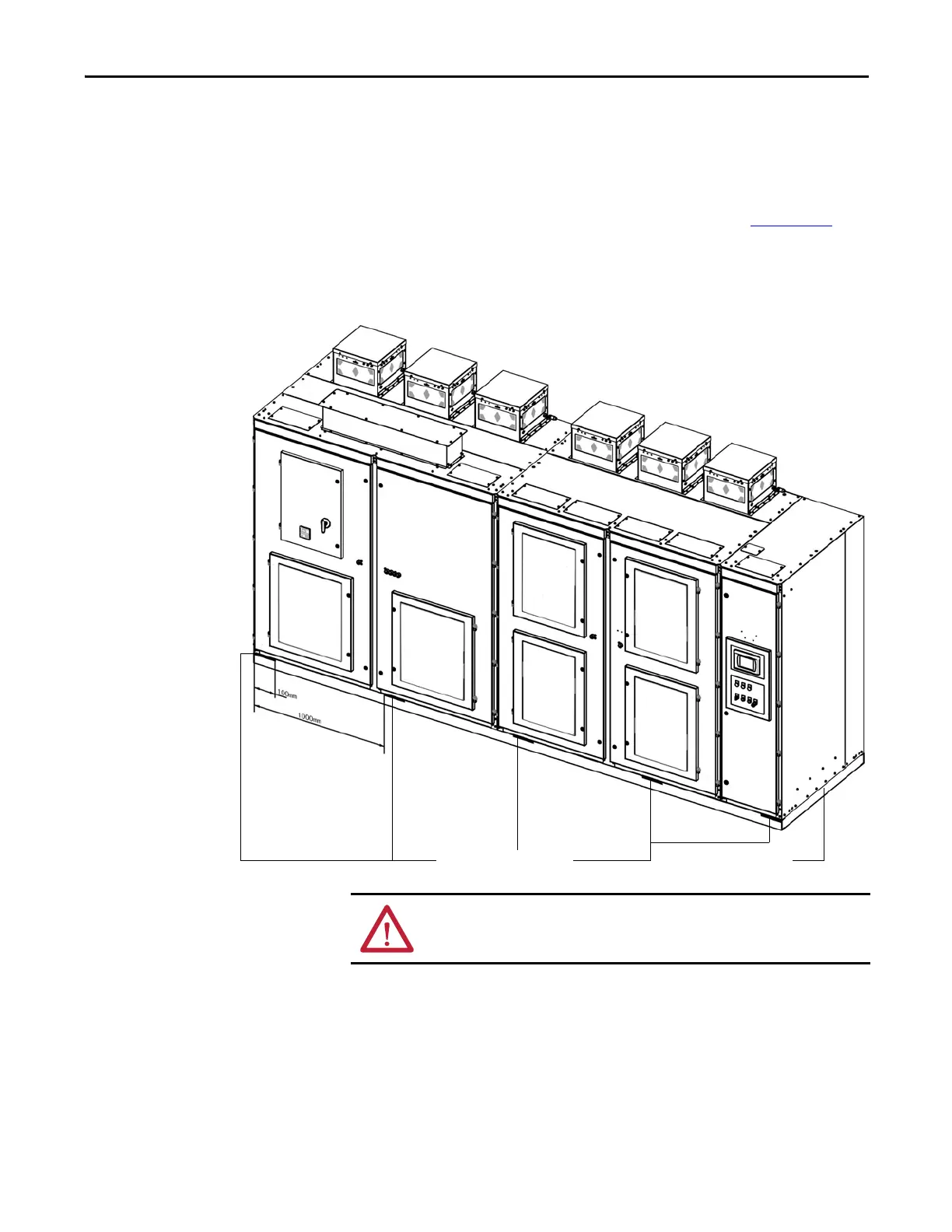
Each weld location should be 100 mm (3.9 in.) for every 1000 mm (39.4 in.). See
Mounting Requirements in the PowerFlex 6000 Medium Voltage Variable
Frequency Drive Shipping and Handling Manual, publication 6000-IN008
) for
further information on the steel base and desired trench and mounting
specifications.
Figure 9 - Welding locations
Channel steel baseRecommended weld locations
ATTENTION: Failure to correctly anchor the cabinet may result in damage to the
equipment or injury to personnel.

 Loading...


