Rockwell Automation Publication 20A-UM001N-EN-P - July 2013 43
Programming and Parameters Chapter 1
DYNAMIC CONTROL (file D)
Stop/Brake Modes
157 [DC Brake Lvl Sel]
Selects the source for [DC Brake Level].
Default:
Options:
0
0
1
2
“DC Brake Lvl”
“DC Brake Lvl”
“Analog In 1”
“Analog In 2”
155
156
158
159
158 [DC Brake Level]
Defines the DC brake current level injected into
the motor when “DC Brake” is selected as a stop
mode.
The DC braking voltage that is used in this
function is created by a PWM algorithm and can
fail to generate the smooth holding force
needed for some applications. Refer to the
PowerFlex 70 and 700 Adjustable Frequency AC
Drive Reference Manual, publication PFLEX-
RM001.
Important: Frame E drives can be limited to
less than 150% depending on the setting of
parameter 151 [PWM Frequency].
Default:
Min/Max:
Units:
[Rated Amps]
0/[Rated Amps] × 1.5
(Equation yields approximate
maximum value.)
0.1 Amps
155
156
157
159 [DC Brake Time]
Sets the amount of time DC brake current is
“injected” into the motor.
Default:
Min/Max:
Units:
0.0 Secs
0.0/90.0 Secs
0.1 Secs
155…
158
160 [Bus Reg Gain]
[Bus Reg Ki]
Sets the responsiveness of the bus regulator.
Default:
Min/Max:
Units:
450
0/5000
1
161
162
File D
Group
No.
Parameter Name and Description
See page 14 for symbol descriptions
Values
Related
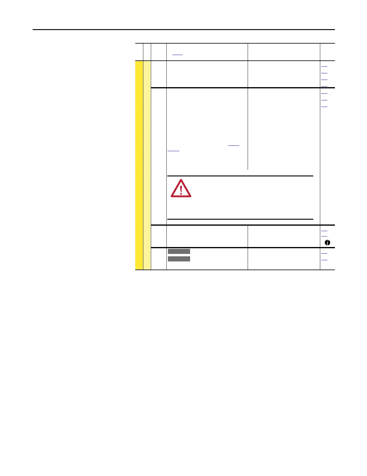
ATTENTION: If a hazard of injury due to movement of
equipment or material exists, an auxiliary mechanical braking
device must be used.
ATTENTION: Do not use this feature with synchronous or
permanent magnet motors. Motors can be demagnetized during
braking.

 Loading...


