44 Rockwell Automation Publication 20A-UM001N-EN-P - July 2013
Chapter 1 Programming and Parameters
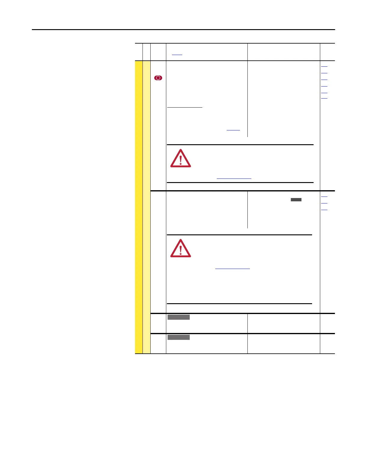
DYNAMIC CONTROL (file D)
Stop/Brake Modes
161
162
[Bus Reg Mode A]
[Bus Reg Mode B]
Active bus regulation mode. Choices are
dynamic brake, frequency adjust or both.
Sequence is determined by programmed value
or digital input programmed for “Bus Reg Md
B.”
Dynamic Brake Setup
If a dynamic brake resistor is connected to the
drive, both these parameters must be set to
either option 2, 3 or 4.
Refer to the Attention statement on page 10 for
important information on bus regulation.
Default:
Options:
1
4
0
1
2
3
4
“Adjust Freq”
“Both-Frq 1st”
“Disabled”
“Adjust Freq”
“Dynamic Brak”
“Both-DB 1st”
“Both-Frq 1st”
155
156
160
163
361…
366
163 [DB Resistor Type]
Selects whether the internal or an external DB
resistor used.
If a dynamic brake resistor is connected to the
drive, P161/162 [Bus Reg Mode x], A, B or Both
(if used), must be set to either option 2, 3 or 4.
Default:
Options:
0
2
0
1
2
“Internal Res”
“None”
“Internal Res”
“External Res”
“None”
161
162
166
164 [Bus Reg Kp]
Proportional gain for the bus regulator. Used to
adjust regulator response.
Default:
Min/Max:
Units:
1500
0/10000
1
165 [Bus Reg Kd]
Derivative gain for the bus regulator. Used to
control regulator overshoot.
Default:
Min/Max:
Units:
1000
0/10000
1
File D
Group
No.
Parameter Name and Description
See page 14 for symbol descriptions
Values
Related
ATTENTI ON: The drive does not offer protection for externally
mounted brake resistors. A risk of fire exists if external braking
resistors are not protected. External resistor packages must be
self-protected. from over temperature or the protective circuit
shown in Figure 1 on page 106
(or equivalent) must be supplied.
ATTENTION: The drive does not offer protection for externally
mounted brake resistors. A risk of fire exists if external braking
resistors are not protected. External resistor packages must be
self-protected from over temperature or the protective circuit
shown in Figure 1 on page 106
, or equivalent, must be supplied.
ATTENTION: Equipment damage can result if a drive mounted
(internal) resistor is installed and this parameter is set to
“External Res.” Thermal protection for the internal resistor is
disabled, resulting in possible device damage.

 Loading...


