Rockwell Automation Publication 20A-UM001N-EN-P - July 2013 69
Programming and Parameters Chapter 1
INPUTS and OUTPUTS (file J)
Digital Inputs
(9)
Typical 3-Wire Inputs - Requires that only 3-wire functions are chosen. Including 2-wire selections causes a
type 2 alarm.
(10)
Typical 2-Wire Inputs - Requires that only 2-wire functions are chosen. Including 3-wire selections causes a
type 2 alarm.
(11)
A “Dig In ConflictB” alarm occurs if a “Start” input is programmed without a “Stop” input. Type 2 Alarms -
Some digital input programming can cause conflicts that result in a Type 2 alarm. Example: [Digital In1 Sel]
set to 5 “Start” in 3-wire control and [Digital In2 Sel] set to 7 “Run” in 2-wire. Refer to Alarm Descriptions on
page 83 for information on resolving this type of conflict.
(12)
Refer to Option Definitions on page 71.
(13)
Enhanced firmware revision V3.002 and later.
(14)
Enhanced firmware revision V5.001 and later.
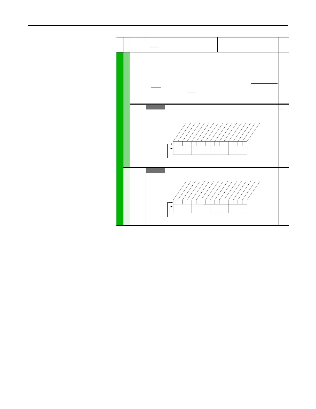
411 [DigIn DataLogic]
Provides data to the logical operations that are done with the digital inputs when parameter
056 option 9 “DigIn DatLog” is set to 1.
056
Digital Outputs
379 [Dig Out Setpt]
Controls output relays (CRx) when parameter 380 or 384 is set to option 30 “Param Cntl”.
File J
Group
No.
Parameter Name and Description
See page 14 for symbol descriptions
Values
Related
000000xx000000xx
10 01234567891112131415
1=Logical 1
0=Logical 0
x =Reserved
Bit #
Factory Default Bit Values
In1 ANDdata
In2 ANDdata
In3 ANDdata
In4 ANDdata
In5 ANDdata
In6 ANDdata
In1 ORdata
In2 ORdata
In3 ORdata
In4 ORdata
In5 ORdata
In6 ORdata
Nibble 1Nibble 2Nibble 3Nibble 4
0xx 0xxxxxxxxxxxx
10 01234567891112131415
1=Enabled
0=Disabled
x =Reserved
Bit #
Factory Default Bit Values
Digital Out1
Digital Out2
Nibble 1Nibble 2Nibble 3Nibble 4
 Loading...


