24 PowerFlex 700 Adjustable Frequency AC Drive Quick Start
INPUTS & OUTPUTS
Analog Inputs
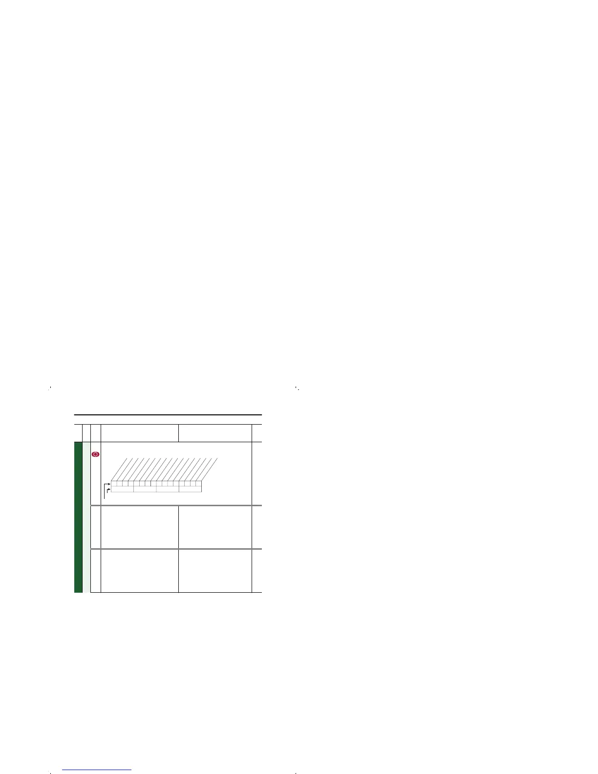
320 [Anlg In Config]
Selects the mode for the analog inputs.
322
325
323
326
322
325
[Analog In 1 Hi]
[Analog In 2 Hi]
Sets the highest input value to the analog
input x scaling block.
[Anlg In Config], parameter 320 defines if
this input will be –/+10V or 4-20 mA.
Default:
Min/Max:
Units:
10.000 Volt
10.000 Volt
4.000/20.000mA
–/+10.000V
0.000/10.000V
0.001 mA
0.001 Volt
091
092
323
326
[Analog In 1 Lo]
[Analog In 2 Lo]
Sets the lowest input value to the analog
input x scaling block.
[Anlg In Config], parameter 320 defines if
this input will be –/+10V or 4-20 mA.
Default:
Min/Max:
Units:
0.000 Volt
0.000 Volt
4.000/20.000mA
–/+10.000V
0.000/10.000V
0.001 mA
0.001 Volt
091
092
File
Group
No.
Parameter Name & Description Values
Related
0xx 0xxxxxxxxxxxx
10 01234567891112131415
1 = Current
0 = Voltage
x =Reserved
Bit #
Factory Default Bit Values
A
nalog
In
1
A
nalog
In
2

 Loading...


