Programming and Parameters 3-33
DYNAMIC CONTROL
Stop/Brake Modes
158 [DC Brake Level]
Defines the DC brake current level
injected into the motor when “DC Brake”
is selected as a stop mode.
The DC braking voltage used in this
function is created by a PWM algorithm
and may not generate the smooth
holding force needed for some
applications. Refer to the PowerFlex
Reference Manual.
Default:
Min/Max:
Units:
[Rated Amps]
0/[Rated Amps] × 1.5
(Equation yields
approximate maximum
value.)
0.1 Amps
159 [DC Brake Time]
Sets the amount of time DC brake current
is “injected” into the motor.
Default:
Min/Max:
Units:
0.0 Secs
0.0/90.0 Secs
0.1 Secs
155
thru
158
160 [Bus Reg Ki]
Sets the responsiveness of the bus
regulator.
Default:
Min/Max:
Units:
450
0/5000
1
161
162
161
162
[Bus Reg Mode A]
[Bus Reg Mode B]
Sets the method and sequence of the DC
bus regulator voltage. Choices are
dynamic brake, frequency adjust or both.
Sequence is determined by programming
or digital input to the terminal block.
Dynamic Brake Setup
If a dynamic brake resistor is connected
to the drive, both of these parameters
must be set to either option 2, 3 or 4.
Refer to the Attention statement on page
P-4
for important information on bus
regulation.
Default:
Options:
1
4
0
1
2
3
4
“Adjust Freq”
“Both-Frq 1st”
“Disabled”
“Adjust Freq”
“Dynamic Brak”
“Both-DB 1st”
“Both-Frq 1st”
160
163
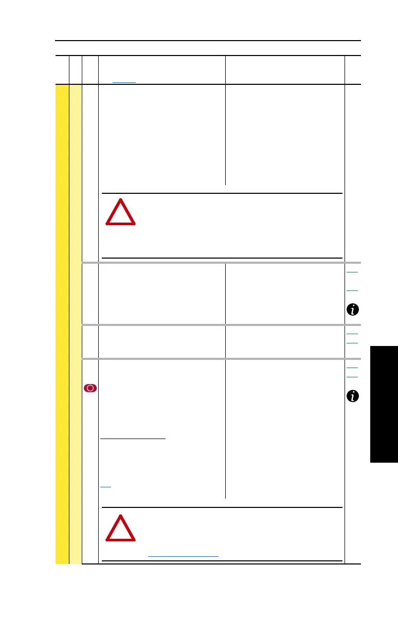
File
Group
No.
Parameter Name & Description
See page 3-2 for symbol descriptions
Values
Related
!
ATTENTION: If a hazard of injury due to movement of equipment
or material exists, an auxiliary mechanical braking device must be
used.
ATTENTION: This feature should not be used with synchronous or
permanent magnet motors. Motors may be demagnetized during
braking.
!
ATTENTION: The drive does not offer protection for externally
mounted brake resistors. A risk of fire exists if external braking
resistors are not protected. External resistor packages must be
self-protected from over temperature or the protective circuit shown
in Figure C.1 on page C-1
(or equivalent) must be supplied.
 Loading...


