3-34 Programming and Parameters
DYNAMIC CONTROL
Stop/Brake Modes
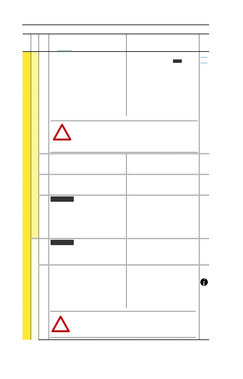
163 [DB Resistor Type]
Selects whether the internal or an
external DB resistor will be used.
Important: In 0-3 Frame drives, only one
DB resistor can be connected to the
drive. Connecting both an internal &
external resistor could cause damage.
If a dynamic brake resistor is connected
to the drive, [Bus Reg Mode A & B] must
be set to either option 2, 3 or 4.
Default:
Options:
0
2
0
1
2
“Internal Res”
“None”
“Internal Res”
“External Res”
“None”
161
162
164 [Bus Reg Kp]
Proportional gain for the bus regulator.
Used to adjust regulator response.
Default:
Min/Max:
Units:
1500
0/10000
1
165 [Bus Reg Kd]
Derivative gain for the bus regulator.
Used to control regulator overshoot.
Default:
Min/Max:
Units:
1000
0/10000
1
166 [Flux Braking]
Set to use an increase in the motor flux
current to increase the motor losses, and
allow a faster deceleration time when a
chopper brake or regenerative capability
is not available. Can be used as a
stopping or fast deceleration method.
Default:
Options:
0
0
1
“Disabled”
“Disabled”
“Enabled”
Restart Modes
167 [Powerup Delay]
Defines the programmed delay time, in
seconds, before a start command is
accepted after a power up.
Default:
Min/Max:
Units:
0.0 Secs
0.0/30.0 Secs
0.1 Secs
168 [Start At PowerUp]
Enables/disables a feature to issue a
Start or Run command and automatically
resume running at commanded speed
after drive input power is restored.
Requires a digital input configured for
Run or Start and a valid start contact.
Default:
Options:
0
0
1
“Disabled”
“Disabled”
“Enabled”
File
Group
No.
Parameter Name & Description
See page 3-2 for symbol descriptions
Values
Related
Vector
!
ATTENTION: Equipment damage may result if a drive mounted
(internal) resistor is installed and this parameter is set to “External
Res” or “None.” Thermal protection for the internal resistor will be
disabled, resulting in possible device damage. Also see
ATTENTION above.
Vector
Vector
ATTENTION: Equipment damage and/or personal injury may result
if this parameter is used in an inappropriate application. Do not use
this function without considering applicable local, national and
international codes, standards, regulations or industry guidelines.
!
 Loading...


