3-50 Programming and Parameters
COMMUNICATION
Comm Control
274 [DPI Port Sel]
Selects which DPI port reference value
will appear in [DPI Port Value].
Default:
Options: 1-5
“DPI Port 1”
“DPI Port 1-5”
275 [DPI Port Value]
Value of the DPI reference selected in
[DPI Port Sel].
Default:
Min/Max:
Units:
Read Only
–/+32767
1
298 [DPI Ref Select]
Scales DPI on maximum frequency or
maximum speed.
Default:
Options:
0
0
1
“Max Freq”
“Max Freq”
“Max Speed”
299 [DPI Fdbk Select]
Selects DPI units displayed on the “Fdbk”
line of the HIM.
(1)
Vector firmware 3.001 and later.
(2)
Refer to Input/Output Definitions on
page 3-56
.
Default:
Options:
17
0
1
1*
2
3
4
5
6
7
8
9
10
11
12
13
14
15
16
17
18
19
20-23
“Speed Fdbk”
“Output Freq”
“Command Freq”
“Command Spd”
“Output Amps”
“Torque Amps”
“Flux Amps”
“Output Power”
“Output Volts”
“DC Bus Volts”
“PI Reference”
(2)
“PI Feedback”
“PI Error”
“PI Output”
“%Motor OL”
“%Drive OL”
“CommandedTrq”
“MtrTrqCurRef”
(2)
“Speed Ref”
“Speed Fdbk”
“Pulse In Ref”
(2)
“Reserved”
“Scale Block1-4
(1)(2)
Masks & Owners
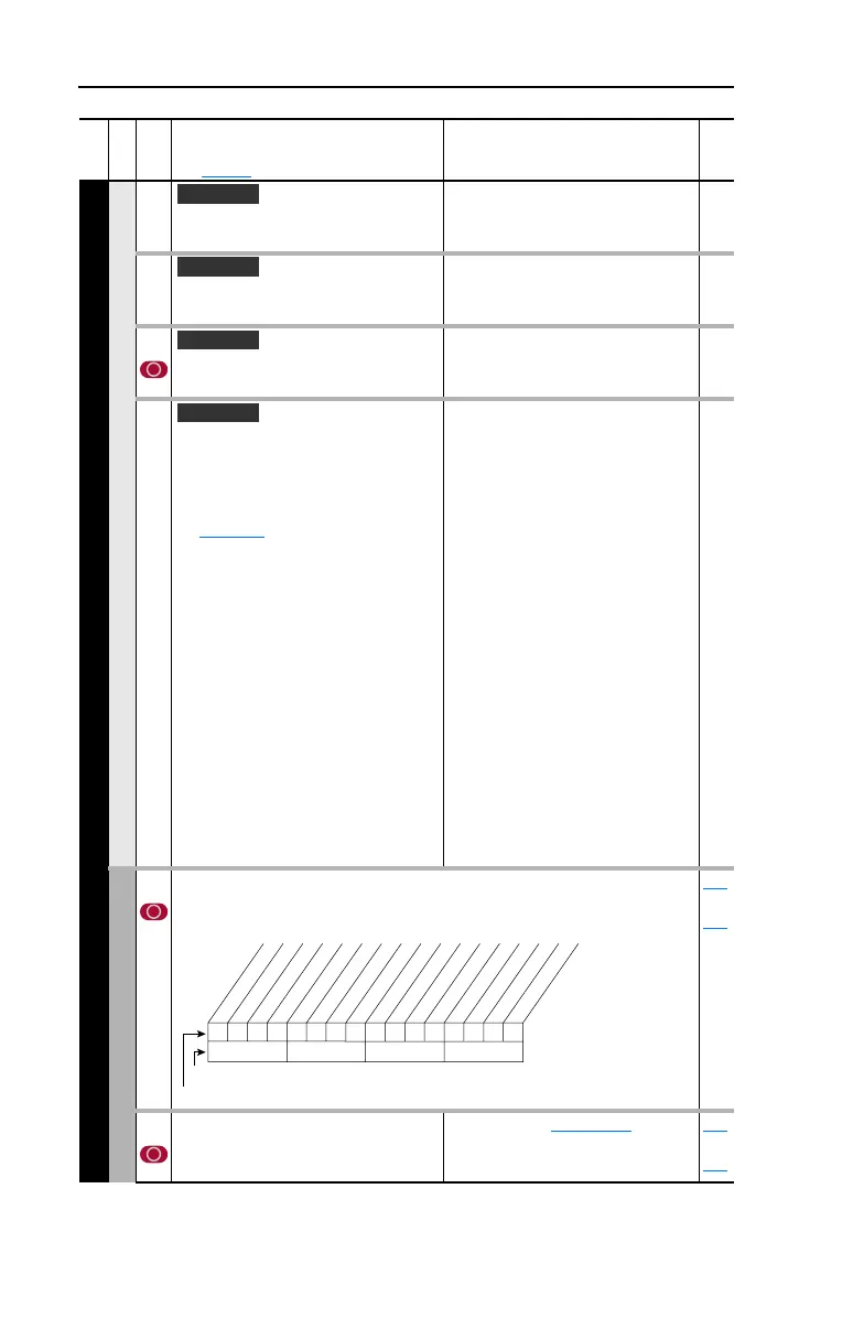
276 [Logic Mask]
Determines which adapters can control the drive. If the bit for an adapter is set to
“0,” the adapter will have no control functions except for stop.
288
thru
297
277 [Start Mask]
Controls which adapters can issue start
commands.
See [Logic Mask]
. 288
thru
297
File
Group
No.
Parameter Name & Description
See page 3-2 for symbol descriptions
Values
Related
Vector
Vector
Vector v3
Vector v3
111111xxxxxxxxxx
10 01234567891112131415
1 =Control Permitted
0 =Control Masked
x =Reserved
Bit #
Factory Default Bit Values
Digital In
DPI Port 1
DPI Port 2
DPI Port 3
DPI Port 4
DPI Port 5
 Loading...


