54 Rockwell Automation Publication 20C-PM001F-EN-P - March 2012
Chapter 2 Programming and Parameters
INPUTS/OUTPUTS
Digital Outputs
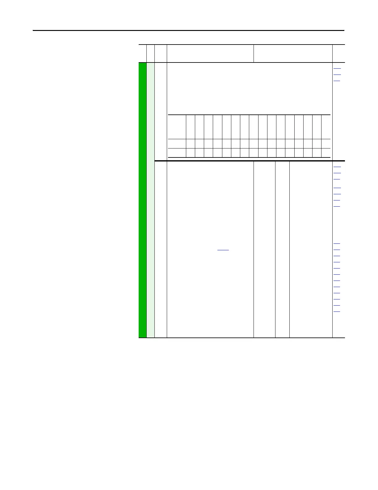
379 [Dig Out Setpt]
Sets the digital output value from a communication device.
Example:
Set [Data In B1] to “379.” The first three bits of this value will determine the setting of [Digital
Outx Sel] which should be set to value 30 “Param Cntl.”
1 = Output Energized
0 = Output De-energized
380
384
388
380
384
388
[Digital Out1 Sel]
[Digital Out2 Sel]
[Digital Out3 Sel]
Selects the drive status that will energize a (CRx)
output relay.
(1 )
Any relay programmed as Fault or Alarm will
energize (pick up) when power is applied to drive
and deenergize (drop out) when a fault or alarm
exists. Relays selected for other functions will
energize only when that condition exists and will
deenergize when condition is removed.
(2)
Activation level is defined in [Dig Outx Level] below.
(3)
Refer to Option Definitions on page 55.
Default:
Options:
1
4
4
1
2
3
4
5
6
7
8
9
10
11
12
13
14
15
16
17
18
19
20
21-26
27
28
29
30
“Fault”
“Run”
“Run”
“Fault”
(1)
“A la rm ”
(1)
“Ready”
“Run”
“Forward Run”
“Reverse Run”
“Auto Restart”
“Powerup Run”
“At Speed”
“At Freq”
(2)
“At Current”
(2)
“At Torque”
“At Temp”
(2)
“At Bus Volts”
(2)
“At PI Error”
(2)
“DC Braking”
“Curr Limit”
“Reserved”
“Motor Overld”
“Power Loss”
“Input 1-6 Link”
“PI Enable”
“PI Hold”
“Reserved”
“Param Cntl”
(3)
381
385
389
382
386
390
383
002
001
003
004
218
012
137
157
147
053
048
184
File
Group
No.
Parameter Name & Description Values
Related
Name
Reserved
Reserved
Reserved
Reserved
Reserved
Reserved
Reserved
Reserved
Reserved
Reserved
Reserved
Reserved
Reserved
Net DigOut3
Net DigOut2
Net DigOut1
Defaultxxxxxxxxxxxxx000
Bit 1514131211109876543210

 Loading...


