PowerFlex® 700S Drives - Phase I Control (Frame Sizes 9 & 10) 35
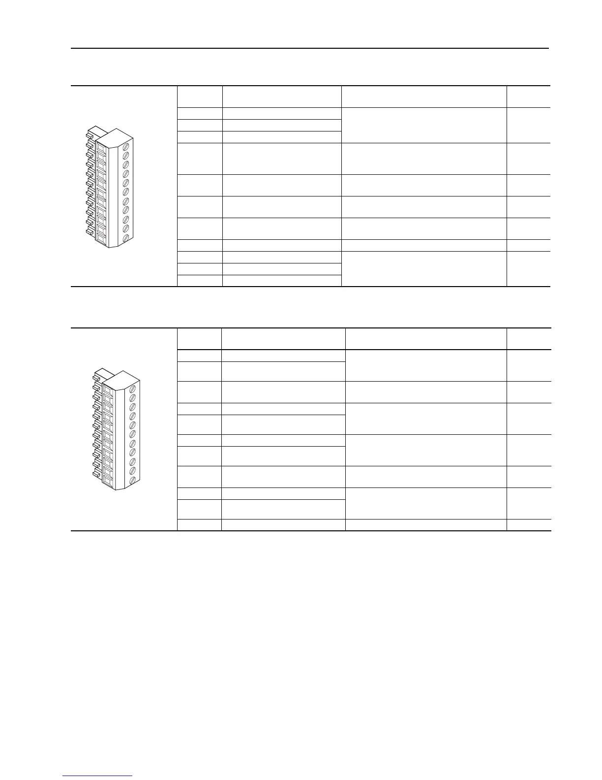
Table J TB1 - Row T (Top) Terminals
Table K TB1 - Row B (Bottom) Terminals
Terminal Signal Description
Related
Parameter
T11 Power Supply 24V DC Return (-) Power and common for pre charge and enable
inputs.
(1)
Inputs may sink or source.
(2)
Rating: 100 mA maximum.
T10 Power Supply 24V DC (+)
T9 Logic Common
T8 Digital Input #1
Default = Precharge
For common DC bus drives. Must be high, for
drive to complete the pre charge cycle.
Load: 20 mA at 24V DC.
824, 838,
829, 826,
827, 828
T7 Enable Input Must be high for drive to run.
Load: 20 mA at 24V DC.
824, 825
T6 Digital Output #1 24V DC open collector (sinking logic) output.
Rating: 25 mA maximum.
843, 844,
824
T5 Digital Output #2 24V DC open collector (sinking logic) output.
Rating: 25 mA maximum.
845, 846,
824
T4 Digital Output Return Return for Digital outputs 1 and 2.
T3 Thermistor Input Used only in FOC2 mode with approved motor for
temperature adaptation.
485
T2 Thermistor Input Return
T1 Thermistor Shield
(1) The drive’s 24V DC power supply supports only on-board digital inputs. Do not use it to power circuits outside of the drive.
(2) Refer to wiring examples of sinking and sourcing outputs.
1110
9
8
7
6
5
43T1 2
Terminal Signal Description
Related
Parameter
B11 Analog Input #1 (-) +/-10.0V DC or +/-1.0V DC bipolar, differential
input.
(1)
, 13 bit + sign, 20k ohm input impedance
800, 801,
802, 803,
804, 805
B10 Analog Input #1 (+)
B9 Analog Input Shield Optional connection point for analog input shield.
(2)
B8 Analog Input #2 (-) +/-10.0V DC or +/-1.0V DC bipolar, differential
input.
(1)
, 13 bit + sign, 20k ohm input impedance
806, 807,
808, 809,
810, 811
B7 Analog Input #2 (+)
B6 Analog Output #1 (+) +/-10.0V DC bipolar, differential output, 11 bit +
sign, 2k ohm minimum load
814, 815,
816, 817,
812, 818
B5 Analog Output #1 Return (-)
B4 Analog Output Shield Optional connection point for analog output
shield.
(2)
B3 Analog Output #2 (+) +/-10.0V DC bipolar, differential output, 11 bit +
sign, 2k ohm minimum load
819, 820,
821, 822,
813, 823
B2 Analog Output #2 Return (-)
B1 Analog Output Shield Optional connection point for analog shields.
(1) Refer to Analog Input Settings in the User Manual - PowerFlex 700S Drives with Phase I Control, publication 20D-UM001, for necessary dip switch settings.
(2) Analog shields should connect to common at the signal source, if possible. Shields for signals from ungrounded devices, such as analog tachometers, should
connect to an analog shield terminal point at the drive.
1110
9
8
7
6
5
43B1 2

 Loading...


