36 PowerFlex® 700S Drives - Phase I Control (Frame Sizes 9 & 10)
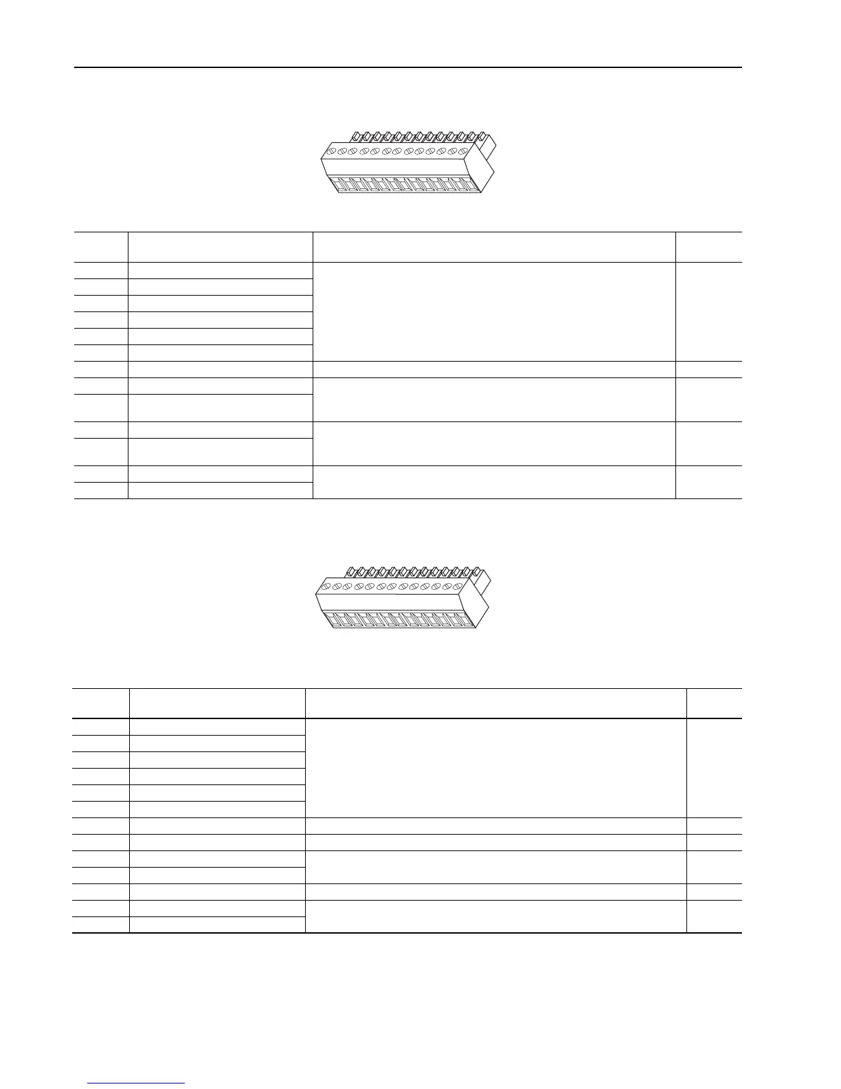
Table L TB2 - Row T (Top) Terminals
Table M TB2 - Row B (Bottom) Terminals
Terminal Signal Description
Related
Parameter
T13 Encoder Signal A Primary encoder interface. 5 or 12V DC switch selectable
(1)
, Nominal current
draw per channel @ 12V DC 45 mA, @5V DC 32 mA
222, 232,
233, 234,
231, 230,
236, 237.
238, 235
T12 Encoder Signal Not A
T11 Encoder Signal B
T10 Encoder Signal Not B
T9 Encoder Signal Z
T8 Encoder Signal Not Z
T7 Shield Connection point for encoder shield.
T6 Digital Input #2 High speed 12-24V DC sinking digital input. 824, 839,
833, 830,
831, 832
T5 Digital Input #2 Return
T4 Digital Input #3 High speed 12-24V DC sinking digital input. 824, 840,
837, 834,
835, 836
T3 Digital Input #3 Return
T2 Power Supply +12V DC (A) (+) 12V DC power supply for primary encoder interface and high speed inputs.
Rating 300 mA
(2)
T1 Power Supply +12V DC Return (A) (-)
(1) Refer to Encoder Input Settings in the User Manual - PowerFlex 700S Drives with Phase I Control, publication 20D-UM001, for necessary dip switch settings.
(2) This power supply supports only the primary encoder interface and digital inputs. Do not use it to power circuits outside of the drive.
T1
2
3
4
5
6
7
8
9
10
11
12
13
Terminal Signal Description
Related
Parameter
B13 Encoder Signal A Secondary encoder interface. 5 or 12V DC switch selectable
(1)
, Nominal current
draw per channel @ 12V DC 45 mA, @5V DC 32 mA
222, 243,
244, 242,
241, 240,
246, 247,
248, 245
B12 Encoder Signal Not A
B11 Encoder Signal B
B10 Encoder Signal Not B
B9 Encoder Signal Z
B8 Encoder Signal Not Z
B7 Shield Connection point for encoder shield.
B6 Unused
B5 Relay Output Relay contact output.
Rating: 5A @ 24V DC Resistive, 2A 24V DC Inductive
824, 841,
842
B4 Relay Output Return
B3 Unused
B2 Power Supply +12V DCDC (B) (+) 12V DC power supply for secondary encoder interface. Rating 300 mA
(2)
B1 Power Supply +12V DC Return (B) (-)
(1) Refer to Encoder Input Setting in the User Manual - PowerFlex 700S Drives with Phase I Control, publication 20D-UM001, for necessary dip switch settings.
(2) This power supply supports only the secondary encoder interface. Do not use it to power circuits outside of the drive
B1
2
3
4
5
6
7
8
9
10
11
12
13

 Loading...


