38 PowerFlex® 700S Drives - Phase I Control (Frame Sizes 9 & 10)
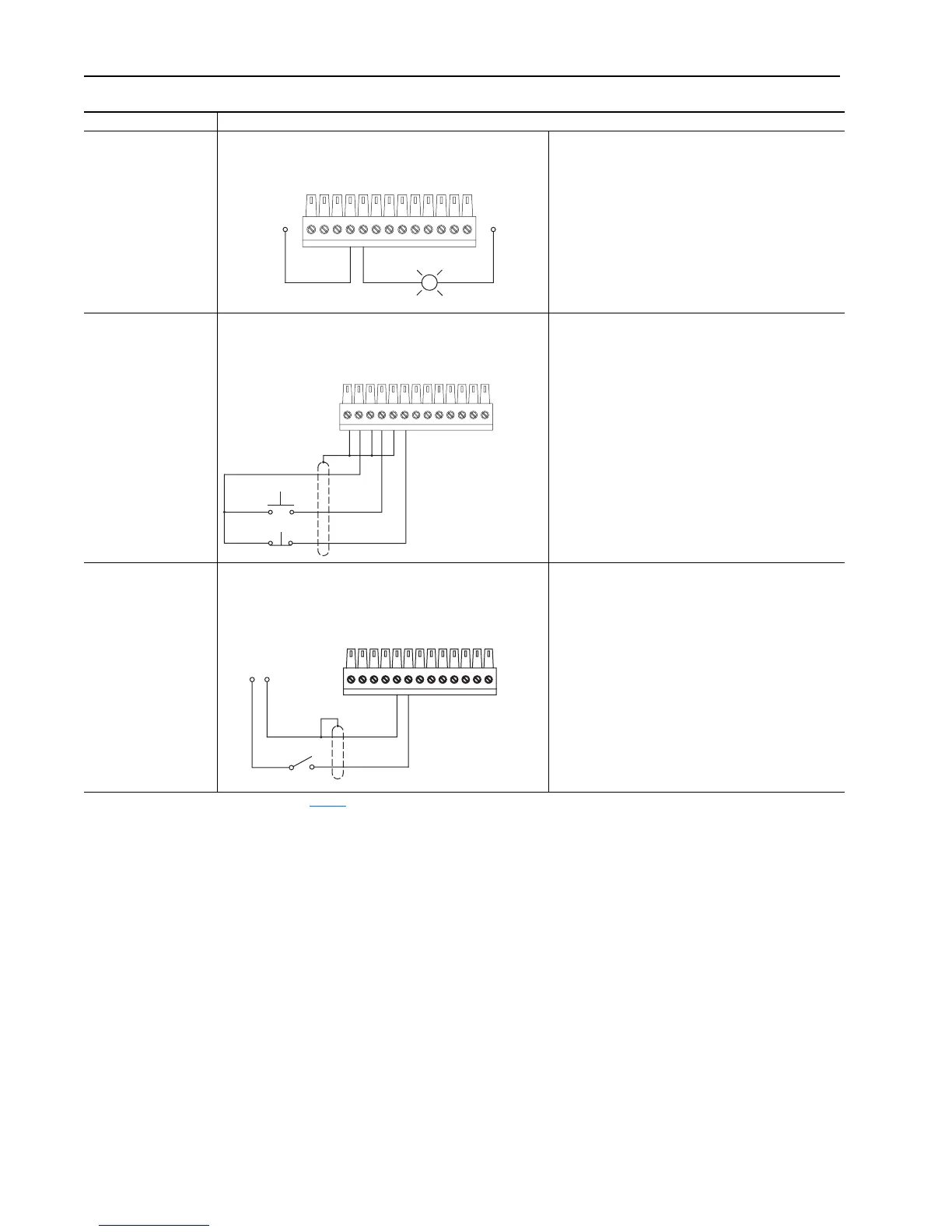
Auxiliary Output -
Relay contact output
Auxiliary Output - sourcing configuration Using Relay Out to annunciate “drive running:”
• Link the status word to the relay control
Par 841 [Relay Out Data] (the destination) linked to
Par 155 [Logic Status] (the source)
• Set Par 842 [Relay Out Bit] to a value of one, so that
Par 155 [Logic Status], bit 1 “Running” will control the
output.
12 - 24V DC Inputs
Digital Inputs used for
Start/Stop 3-Wire
Control
3-Wire Control, Non-Reversing - using internal power supply • Set Par 839 [DigIn2 Sel] = 1 “Normal Stop”
• Set Par 840 [DigIn3 Sel] = 2 “Start”
• Set Par 153 [Control Options], bit 8 “3WireControl” =
1
Use Digital Input 2 & 3 for 3-wire Start/Stop Control
Digital Inputs used for
Run/Stop 2-Wire Control
Note: +12V and +24V
are also available from
TB1 Top 10 & 11.
2 -Wire Control, Non-Reversing - using external power supply
(1)
• Par 839 [DigIn2 Sel] = 3 “Run”
• Par 153 [Control Options], bit 8 “3WireControl” = 0
AND
• Par 153 [Control Options], bit 9 “2W CoastStop” = 0
(ramp stop)
or
• Par 153 [Control Options], bit 9 “2W CoastStop” = 1
(coast stop)
Use Digital Input 2 for 2-wire Run/Stop Control
(1) See “Important” statement about the HIM on page 44.
Input/Output Connection Example
45
Running
EXTERNAL 24V
POWER SUPPLY
EXTERNAL
24V DC
COMMON
(RETURN)
TB2 - Row B (Bottom)
345621
Start
Stop
TB2 - Row T (Top)
POWER
COMMON
(RETURN)
12 OR 24V DC
POWER SUPPLY
56
Run-Stop
TB2 - Row T (Top)

 Loading...


